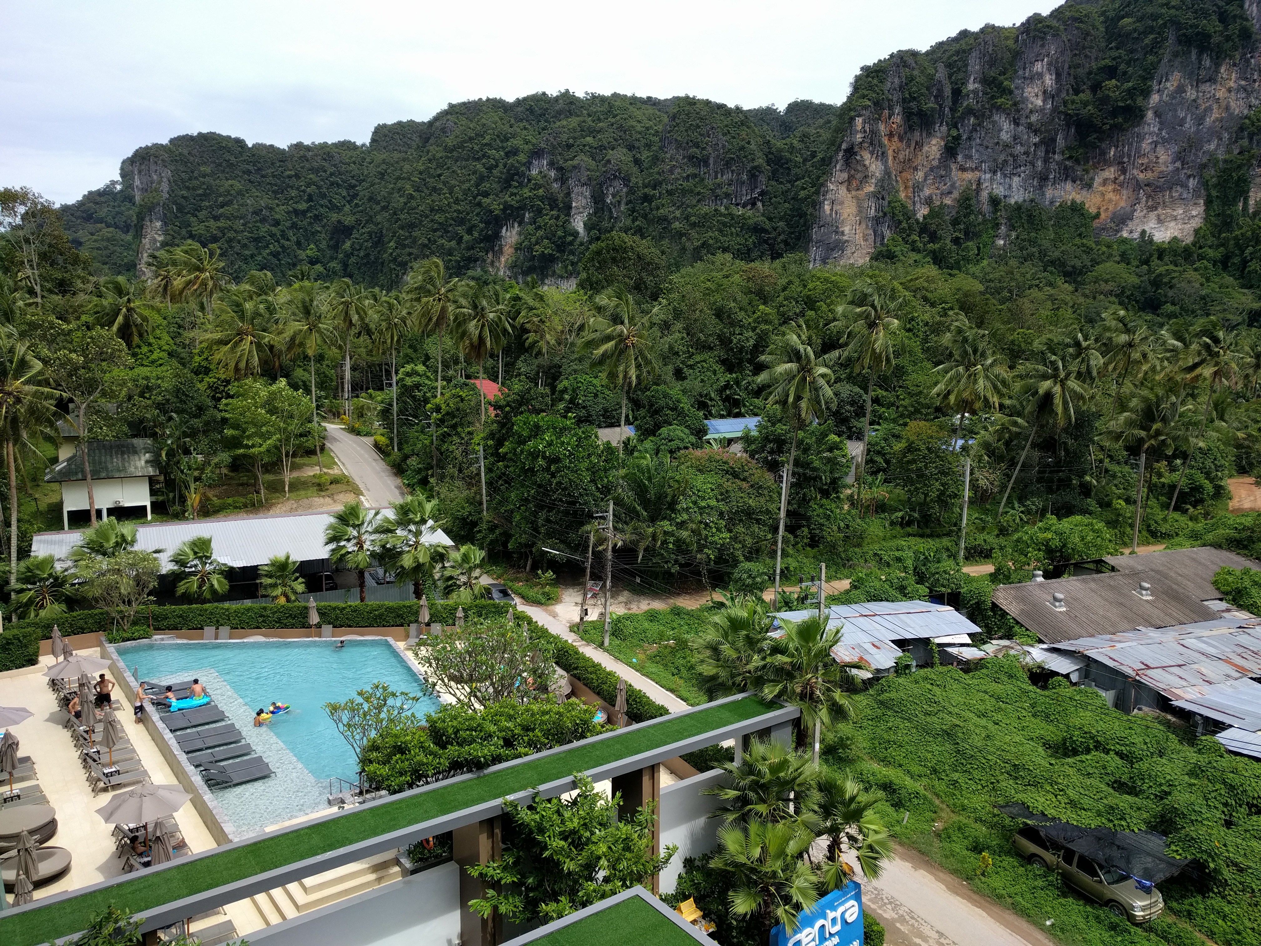
Wedding over we took the first opportunity we could to escape the chaos of Bangkok City and fly out to Ao Nang beach in Krabi province. Massage, snorkeling, streetfood and beer. Not necessarily in that order.
The place where I document the stupid stuff I do
Wedding over we took the first opportunity we could to escape the chaos of Bangkok City and fly out to Ao Nang beach in Krabi province. Massage, snorkeling, streetfood and beer. Not necessarily in that order.

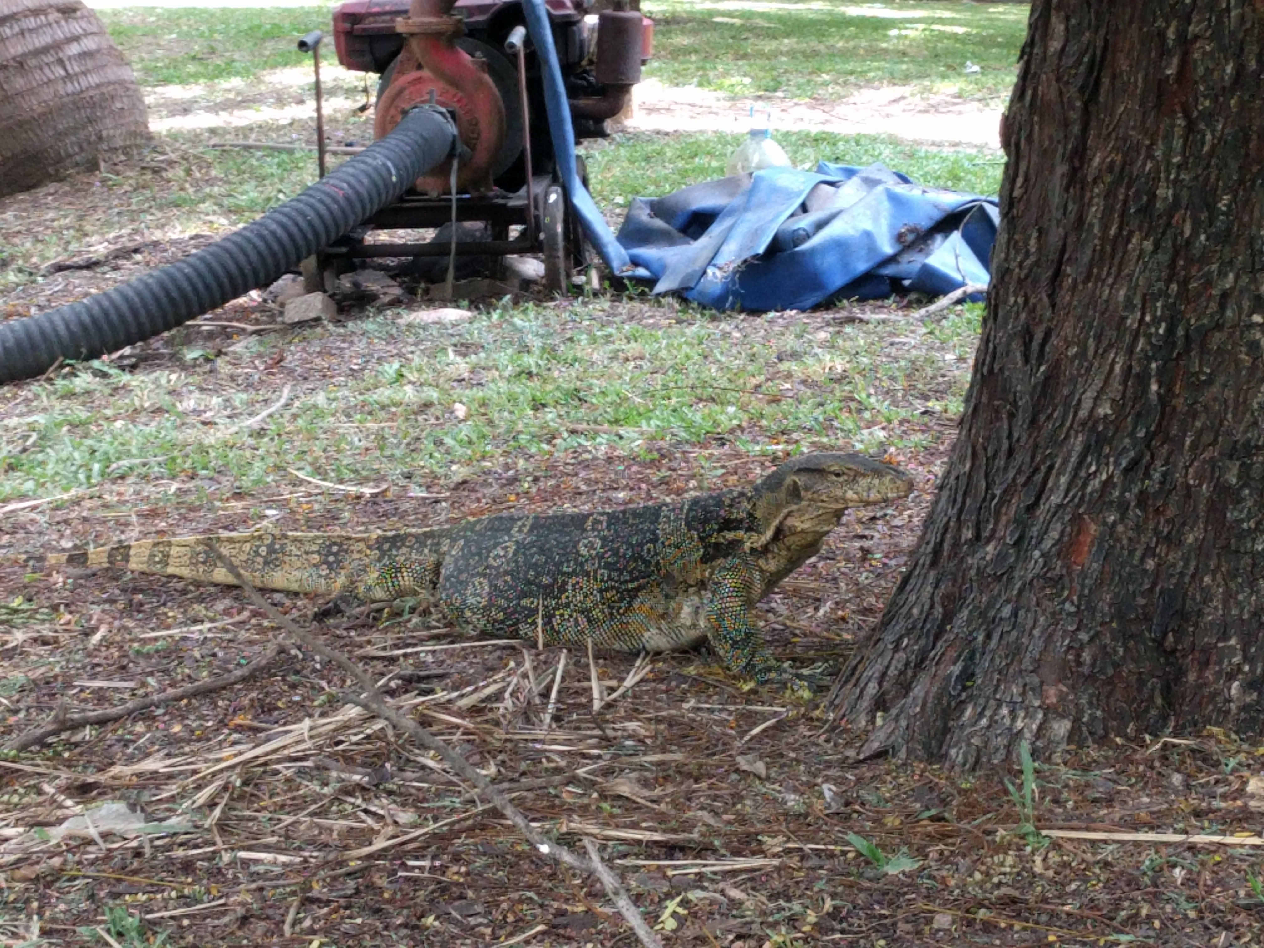
A morning in Lumphini park looking at the monitor lizards and then a crazy tuk tuk ride home. Quick dip in the pool before heading out for a dinner cruise on the Chao Praya River.
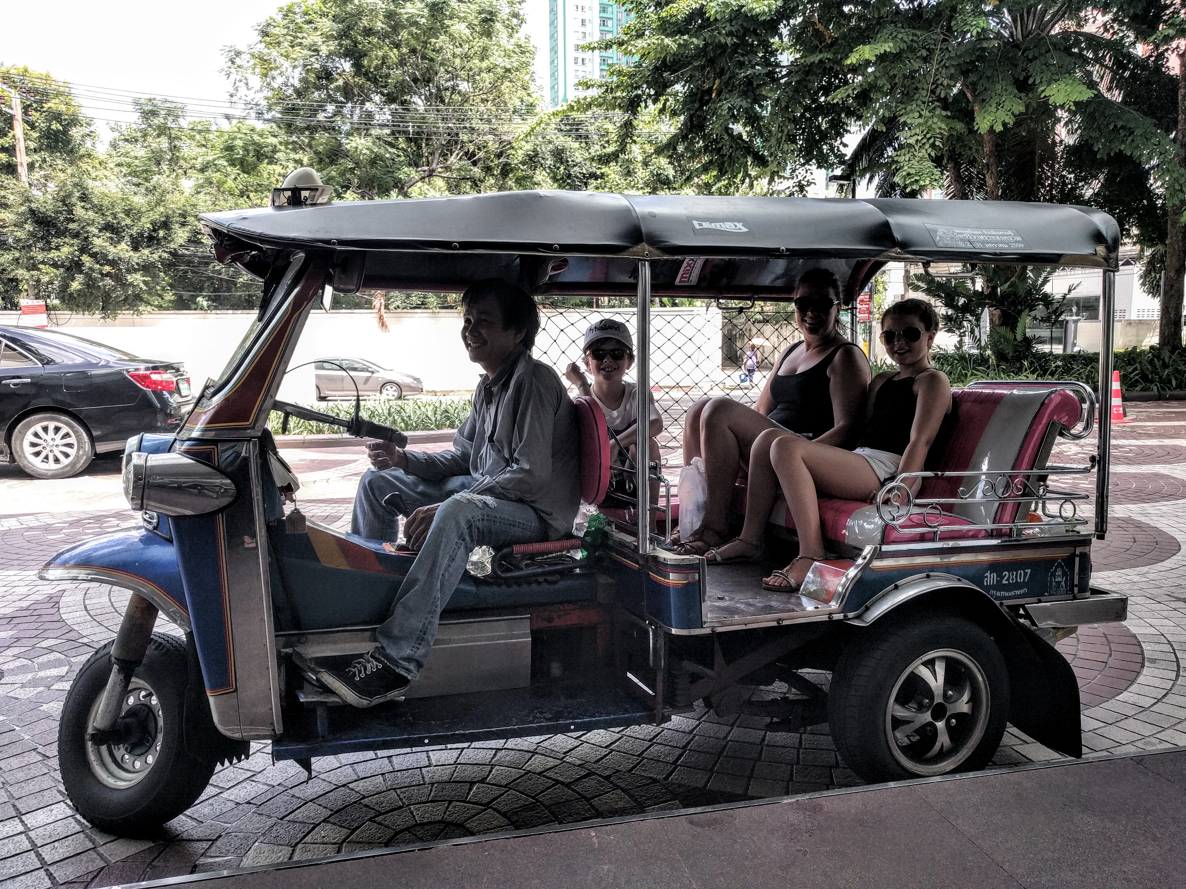
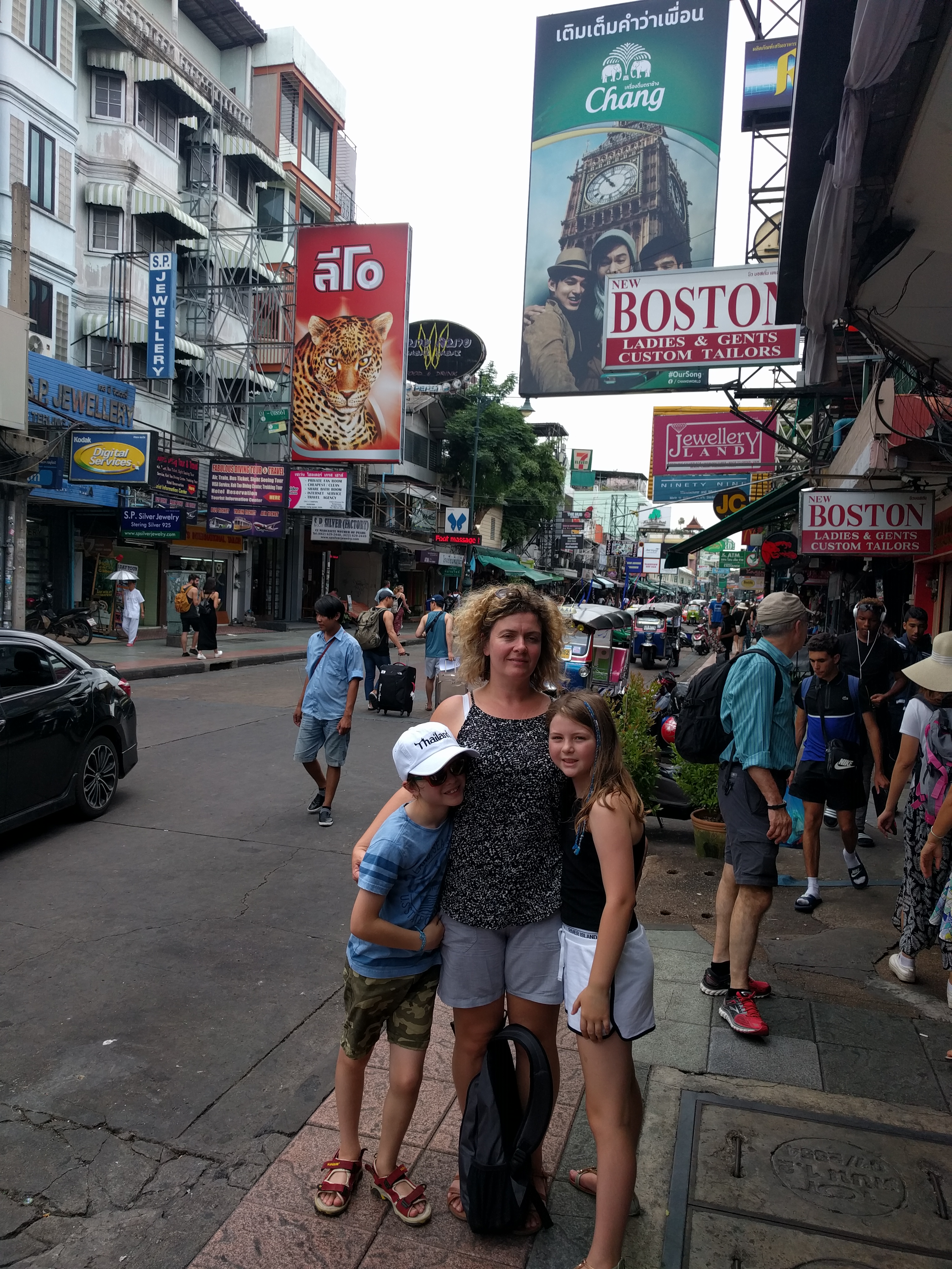
Mooching along Khao San Rd buying sarongs and other assorted tat…..and beer. Arrived via tuk tuk from Wat Poh where we couldn’t get in because we had shorts on. 🙁
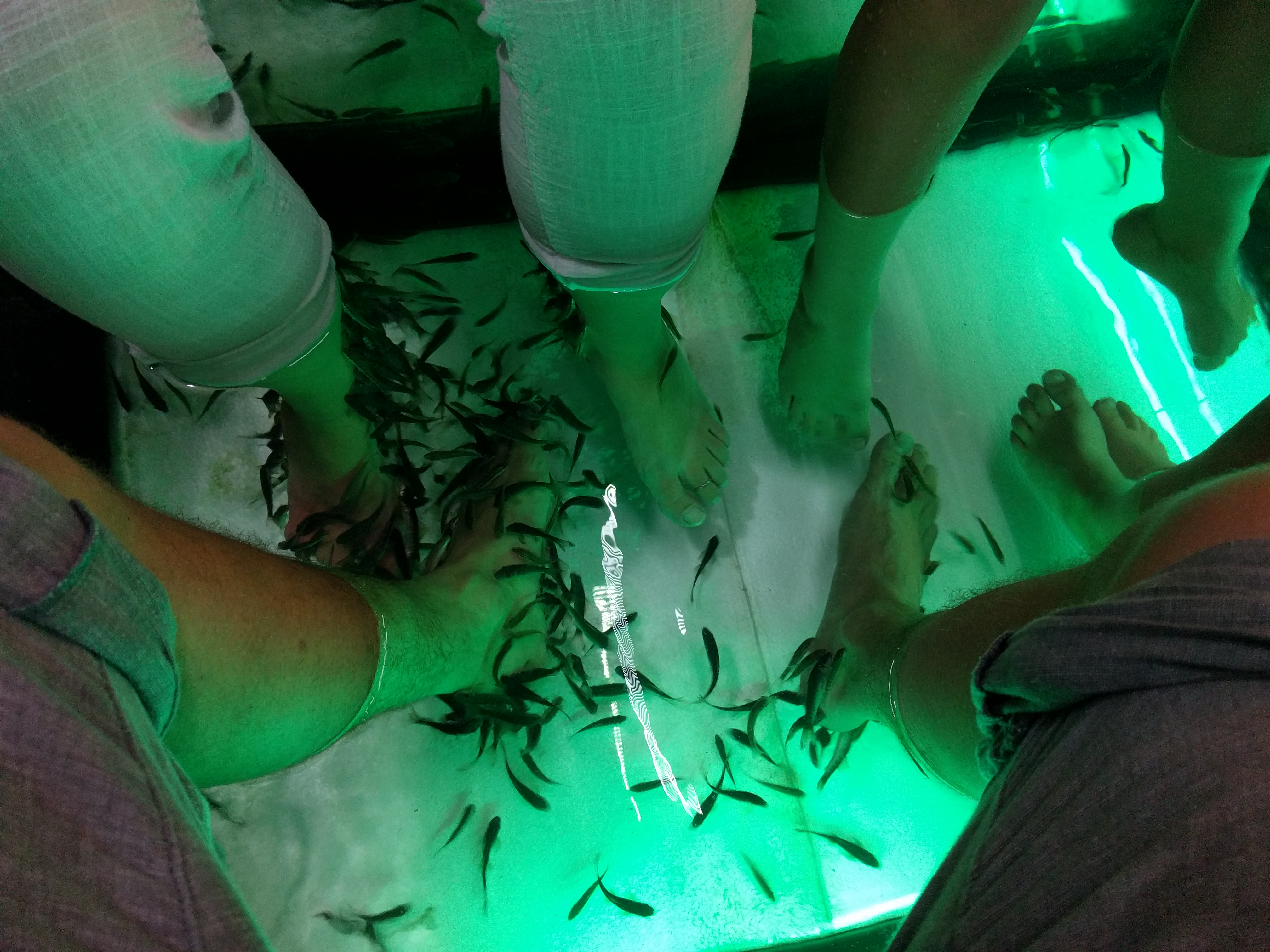
For some reason the fish preferred the old feet of Emma and I. We were in hysterics with the fish nibbling away. Strangest feeling ever
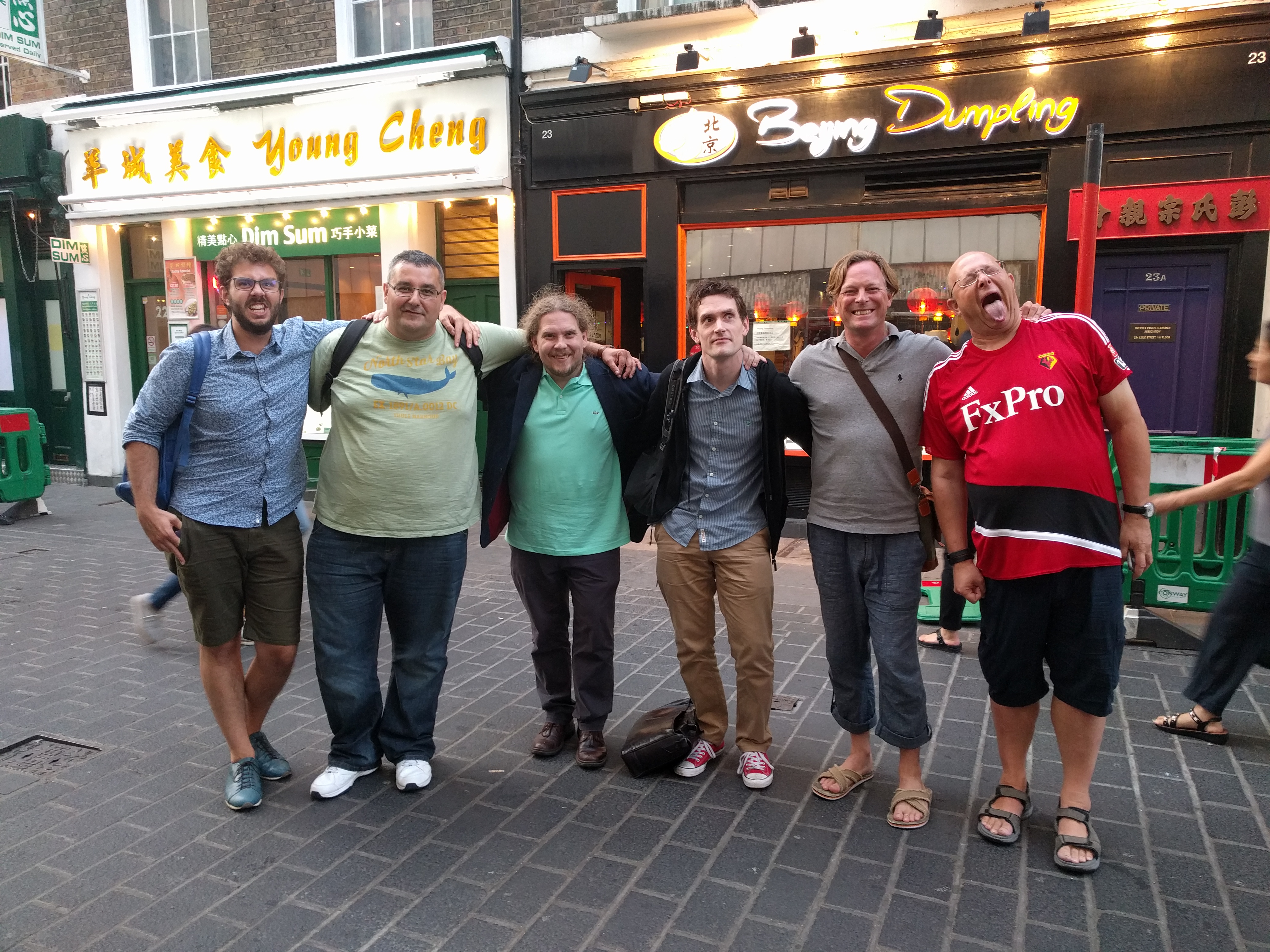
My last night in London for a while was spent in the usual style at my favourite dumpling joint
Each year I tend to try to accomplish something. In 2016 the ambition was to visit the theatre every month. As you can see, I accomplished it. There were a few close calls when I only made it to the theatre by the 29th of the month but nevertheless…..boom!
BTW – Harold Pinter plays…shit

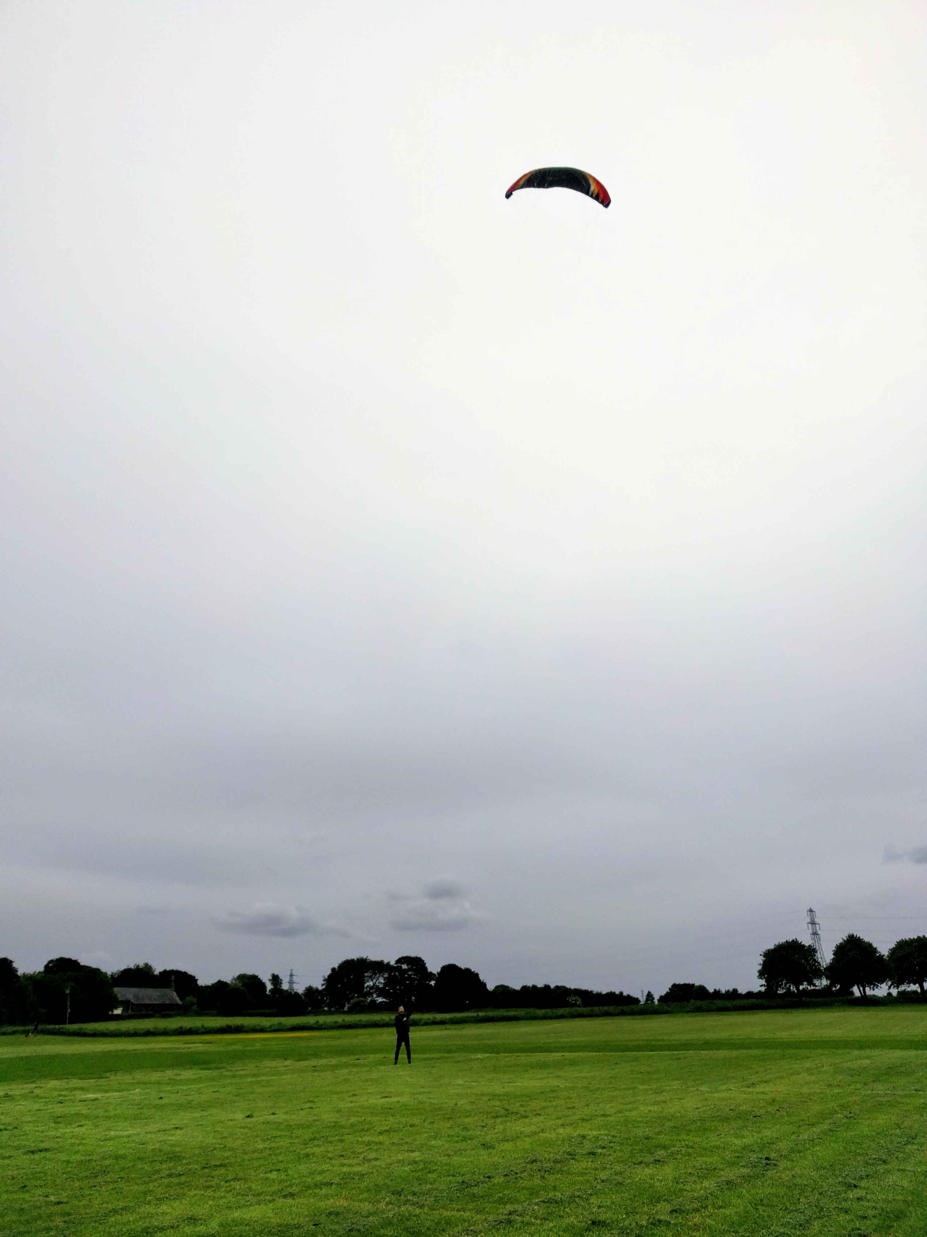
4.9 sq metres of flexifoil goodness
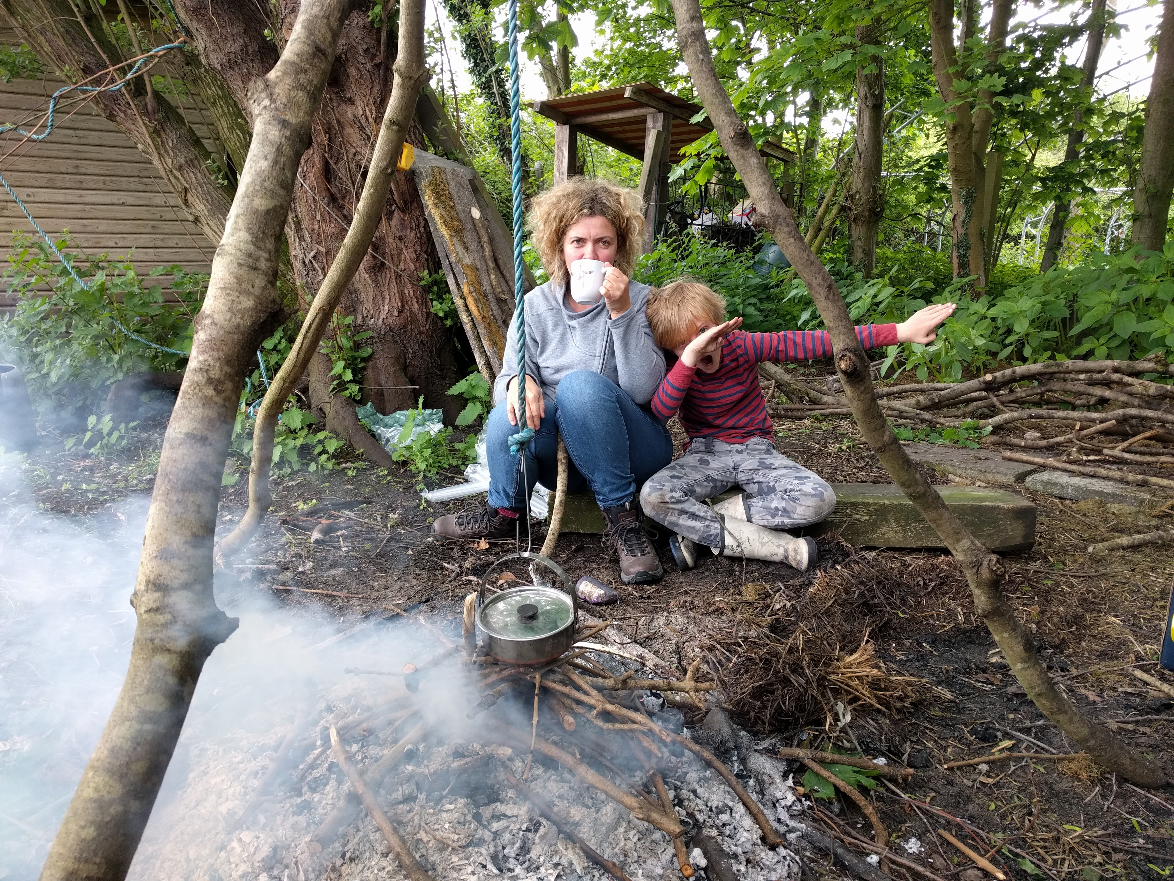
Oliver and I woke up on a Sunday morning and decided what we had to do was make a cup of tea. Outside.
We built a fire and burned off a load of rubbish we wanted to get rid of. Whilst that was going on we found three likely looking branches and sawed them to roughly the right lengths. Recycled some wire from a chain link fence to tie them all together and gave it a whirl.
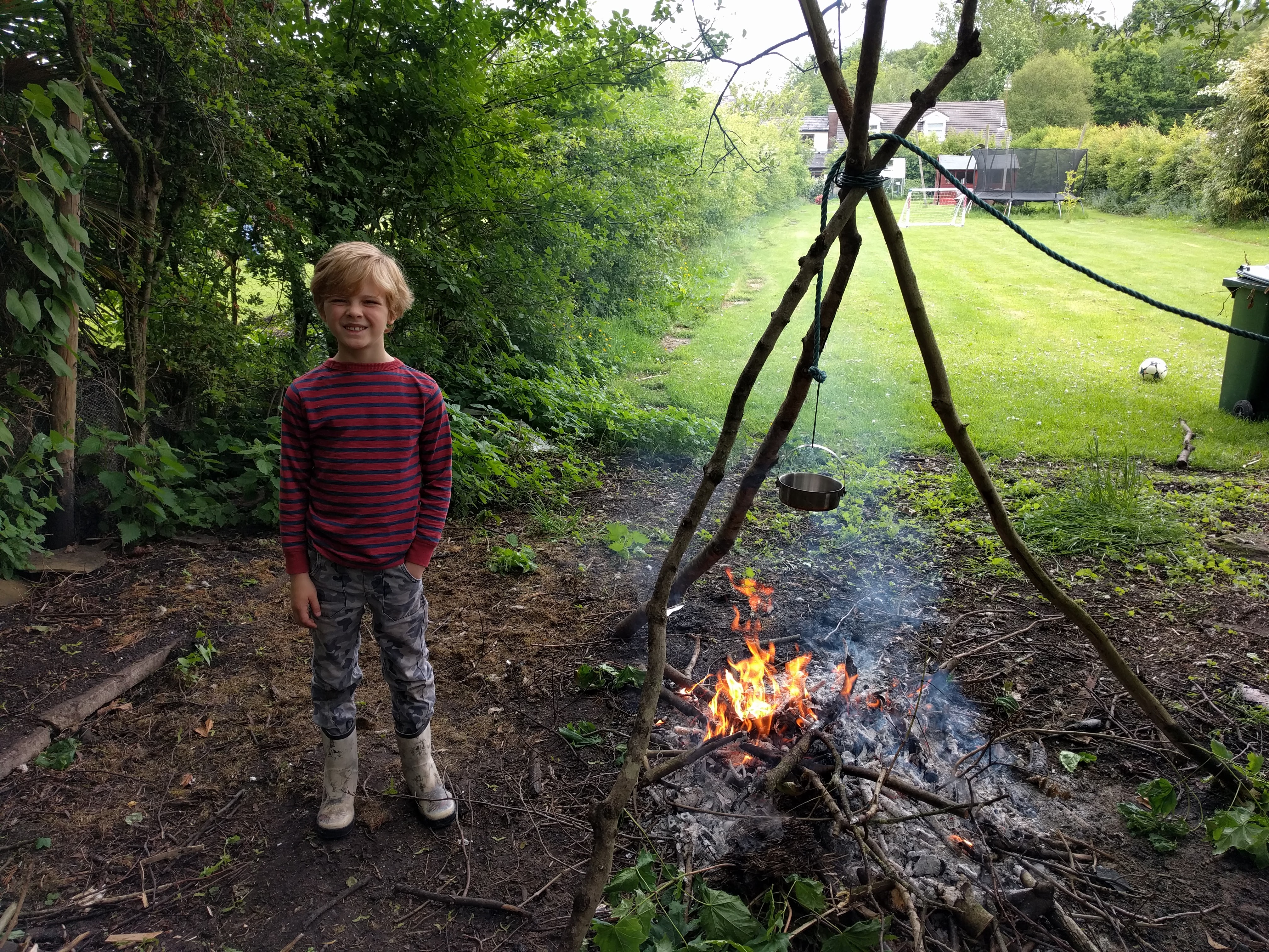
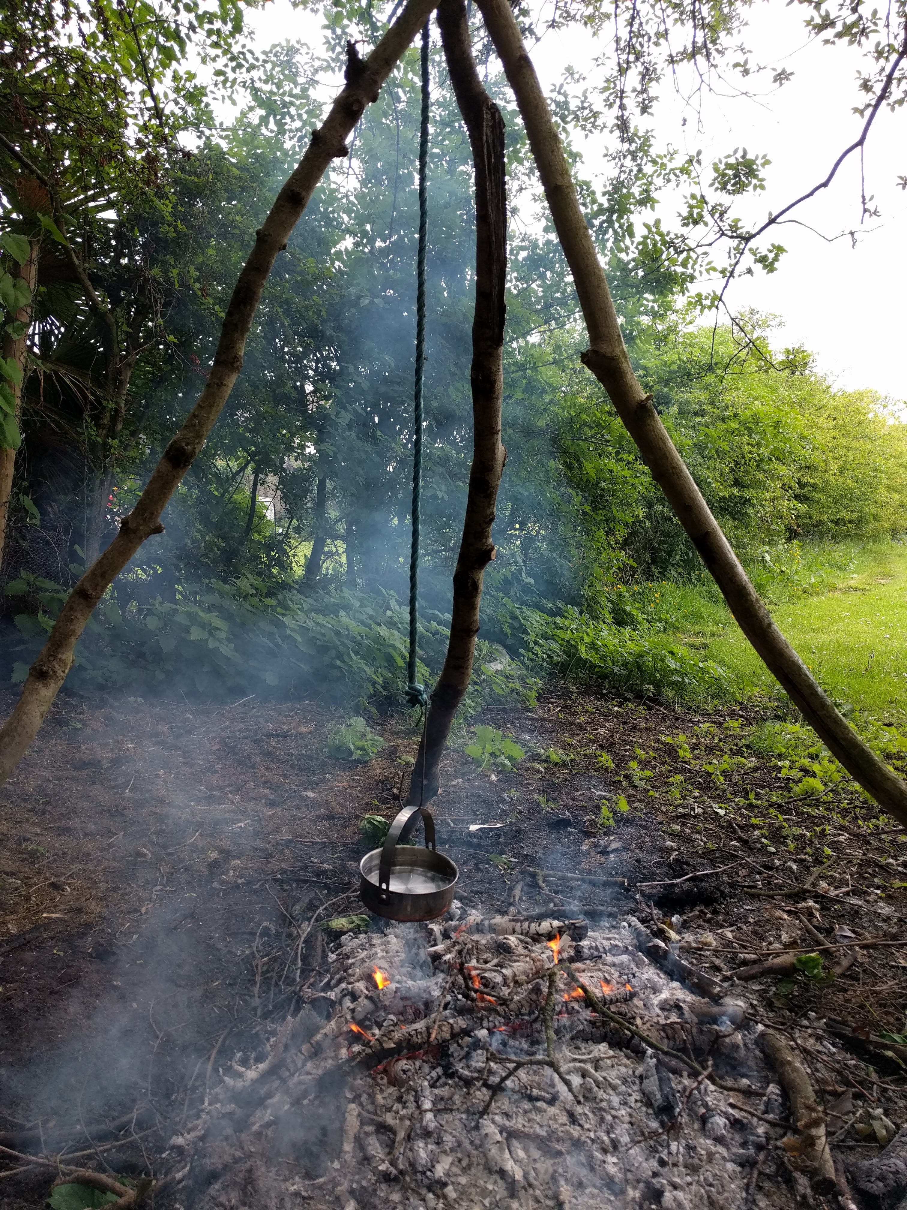
For Mk 1 we were using rope to suspend our Billy can. It worked ok as a short term solution. Also, I forgot to put the lid on.
Emma came down when all the hard work had been done and there was tea that needed drinking. Oli doesn’t really drink tea so he gave a celebratory dab.
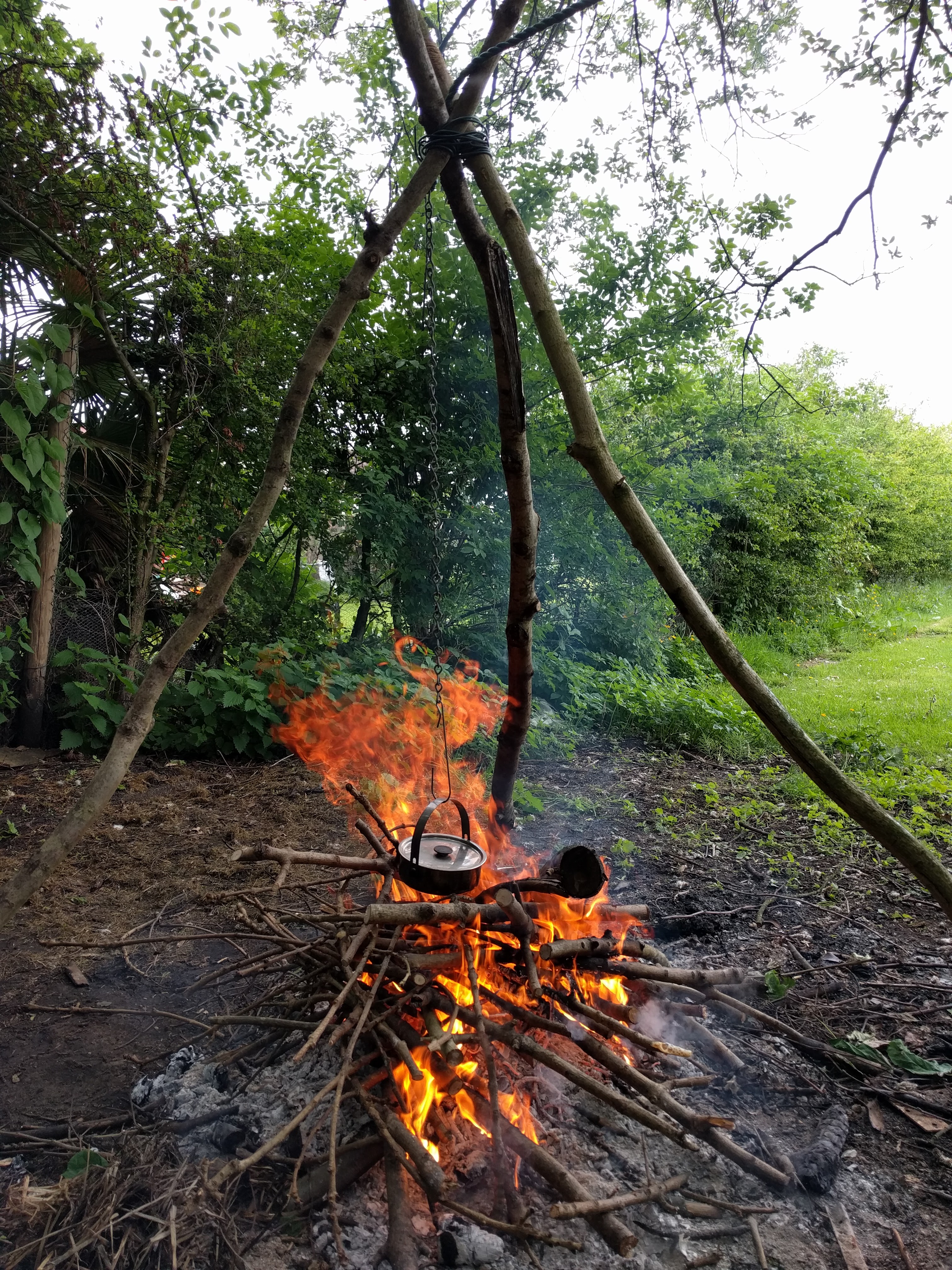
For Mk 2 I recycled some chain off an old gate that I had lying around. We also discovered we could only make one cup of tea per Billy can so this time I made the fire a lot hotter to make my cup of tea more quickly.
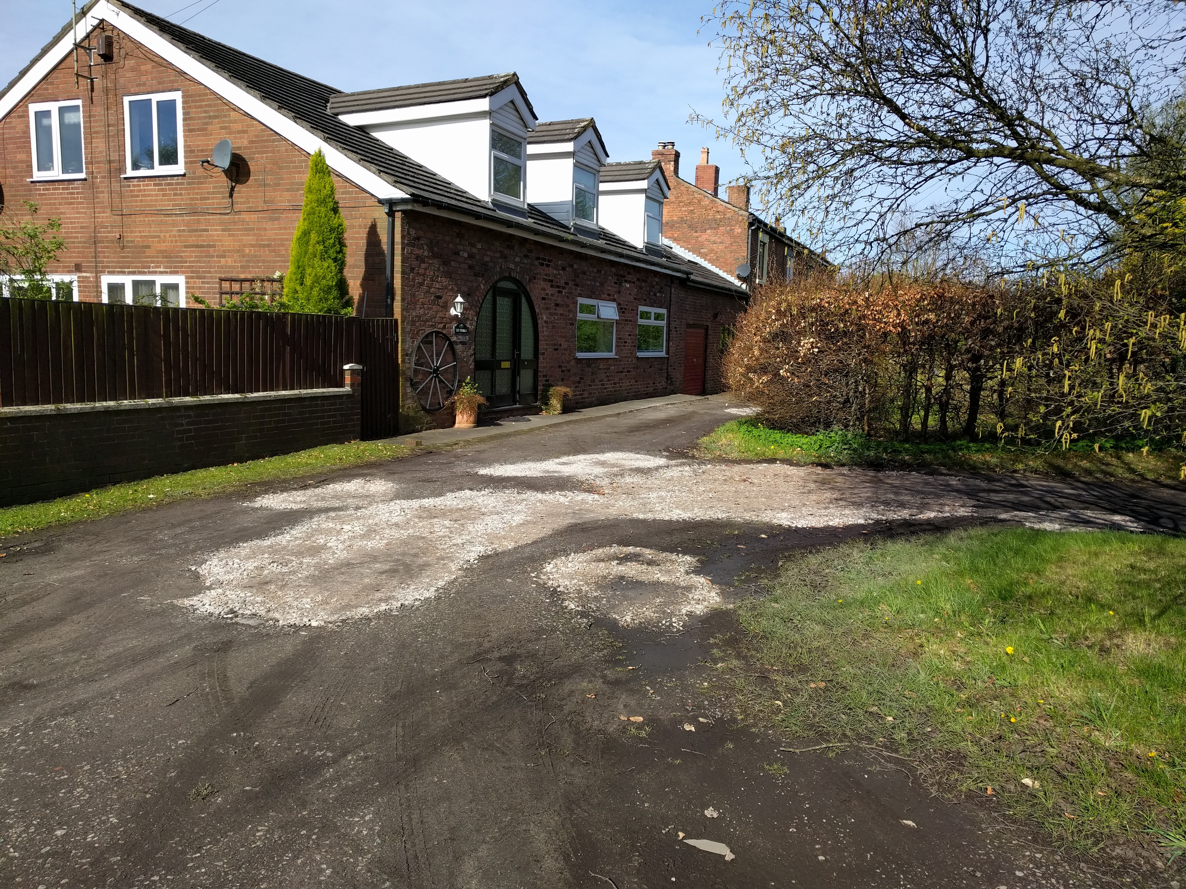
We live on an unadopted road. Over the past few years it’s been getting more and more bumpy. For the past couple of months I’ve been regularly grounding my car when coming in to park so I finally decided to fix it.
I got 4*1000kg bags of MOT Type 1 delivered
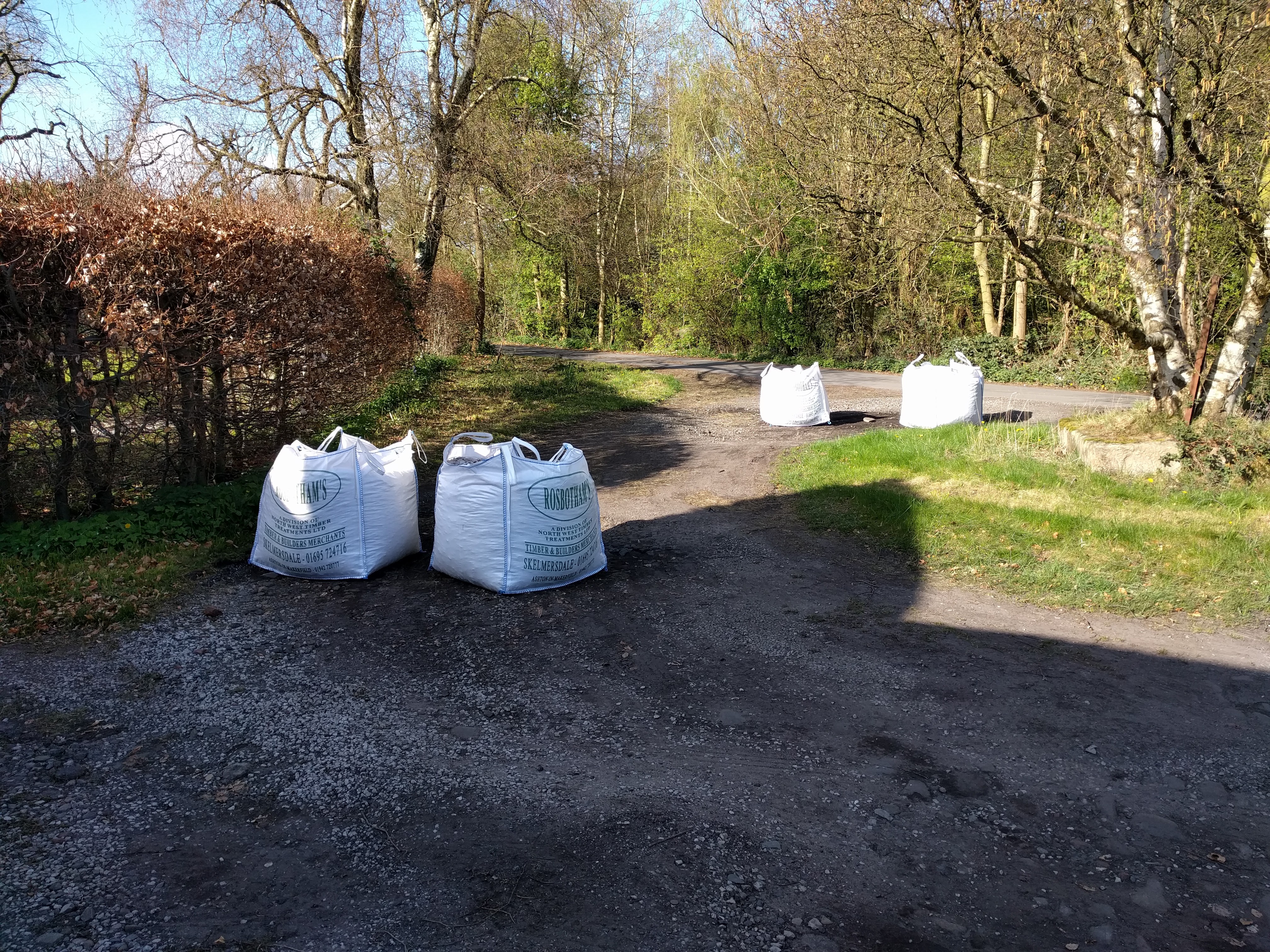
and hired a roller. I was going to use a whacker plate but where’s the fun in that?
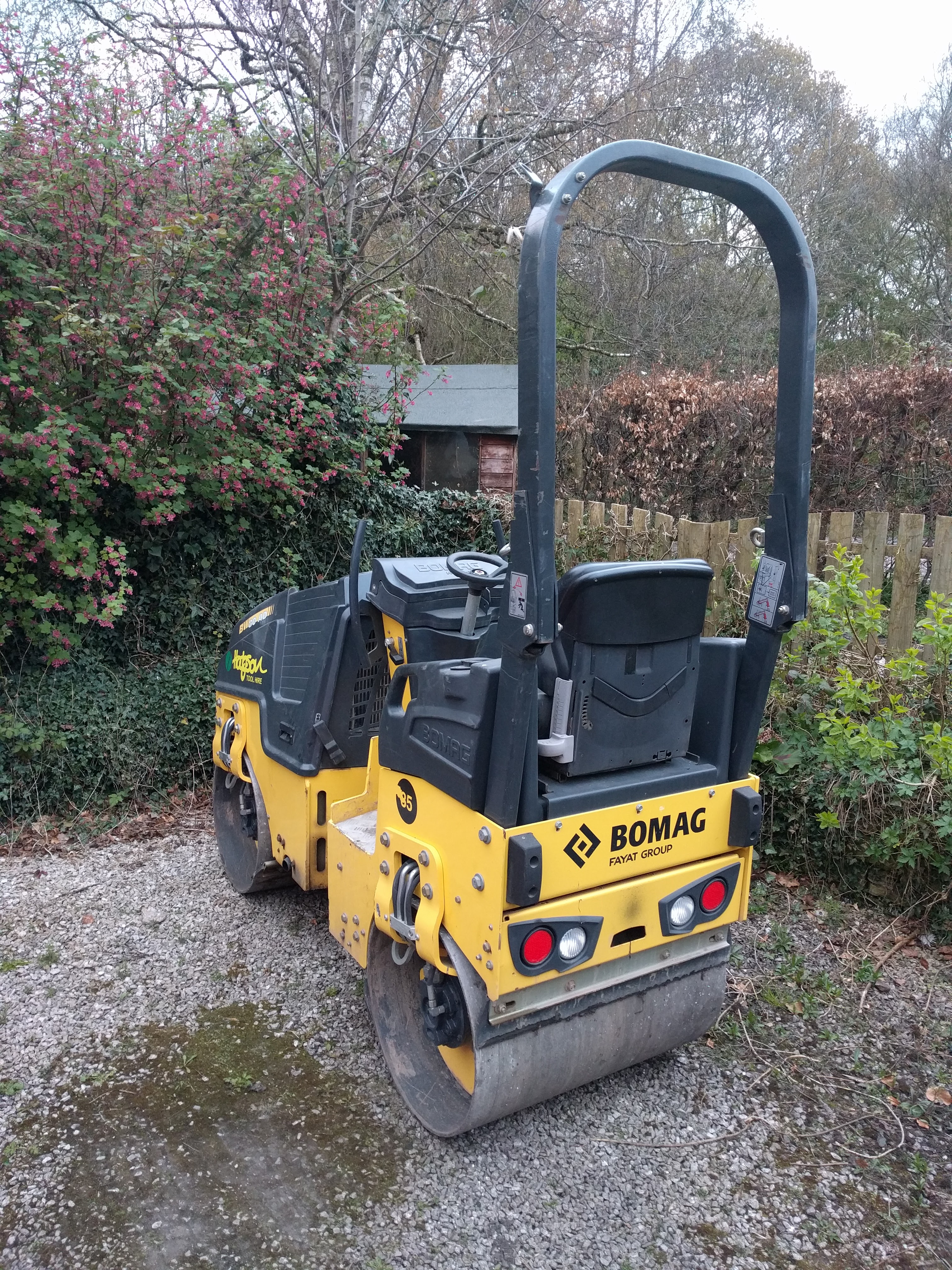
it was then a family effort to get to stoney sandy mix out of the bags and into the right places.
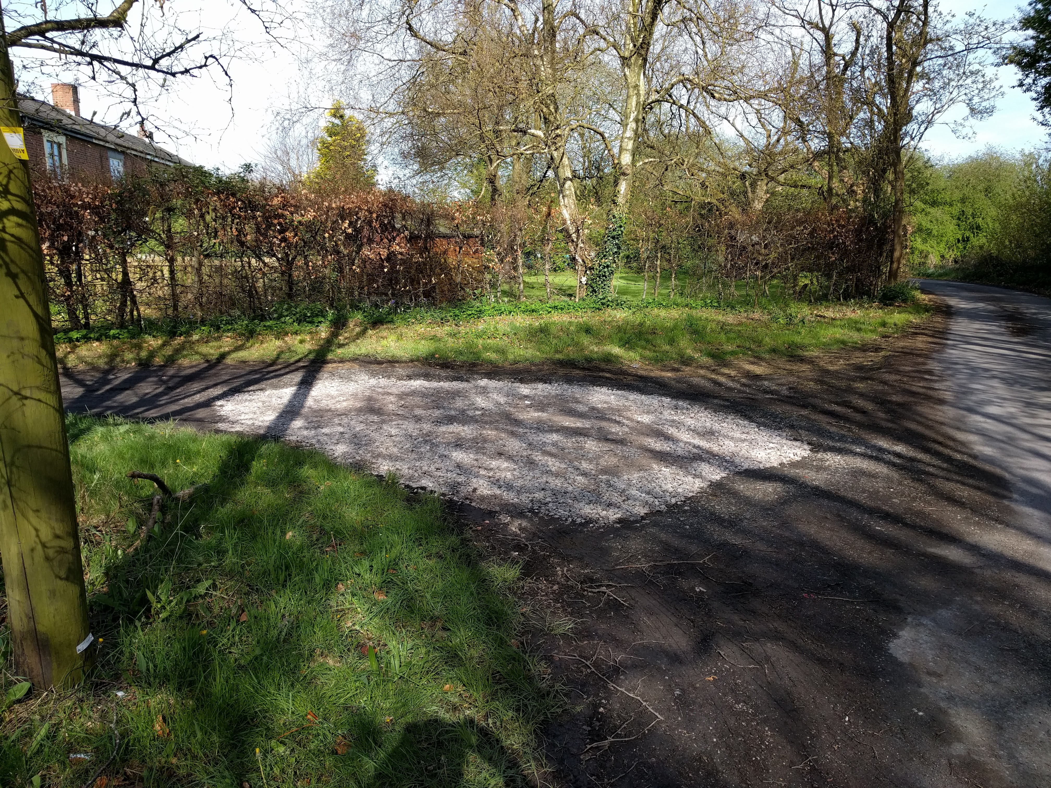
It doesn’t look too great and it isn’t perfectly flat but my car no longer bottoms out when I park it.
Lessons learned:
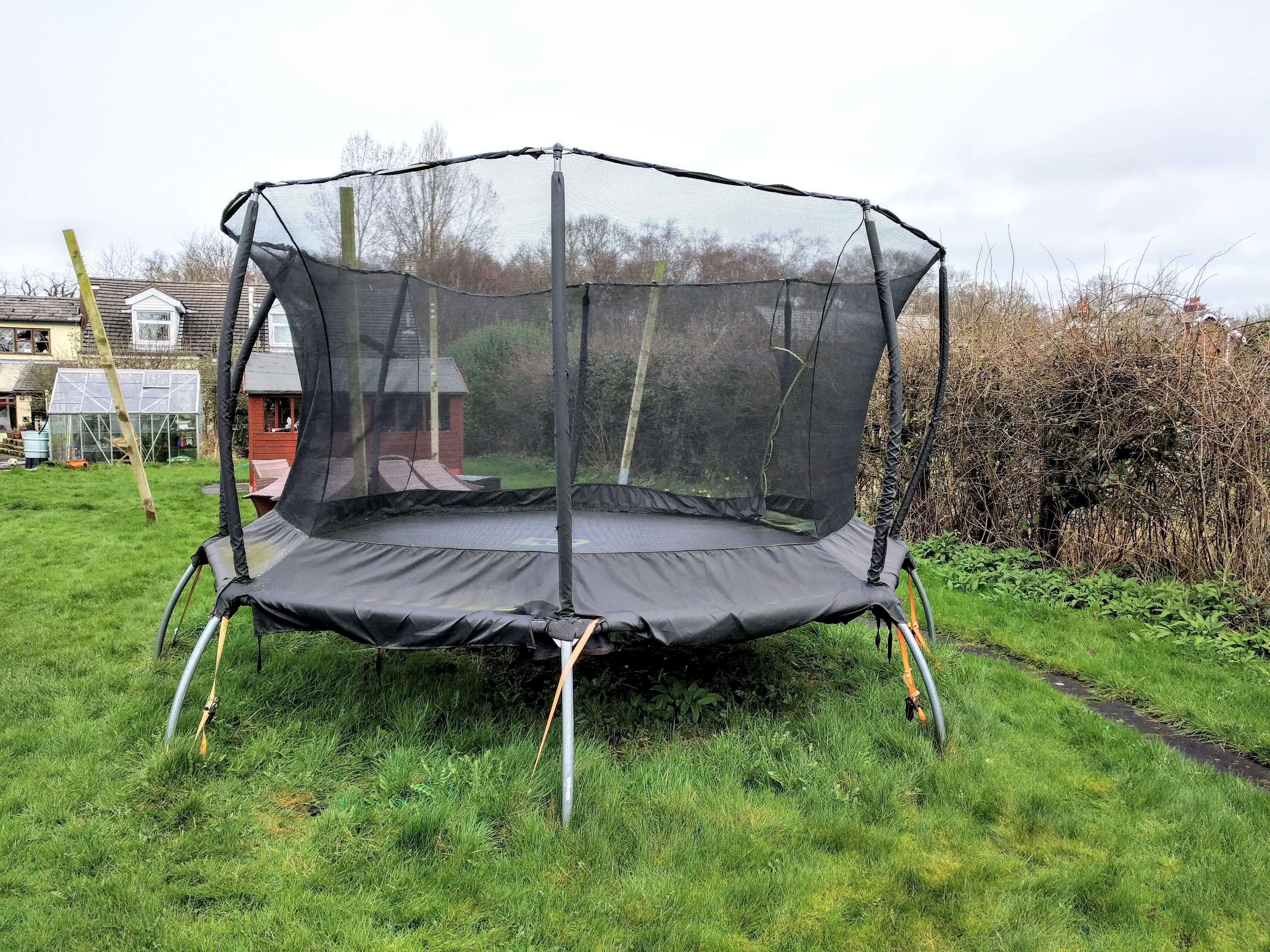
Quite some time ago we had some gales and the trampoline was blown across the garden. It was pretty badly wrecked but I patched it together again. Unfortunately the patching wasn’t quite good enough and it kept falling apart. I’d regularly spend days fixing it again and it would just break again. I finallu decided enough was enough. I decided to fix it one last time and if it broke again then it was going into the bin. So this fix had to be a good one…
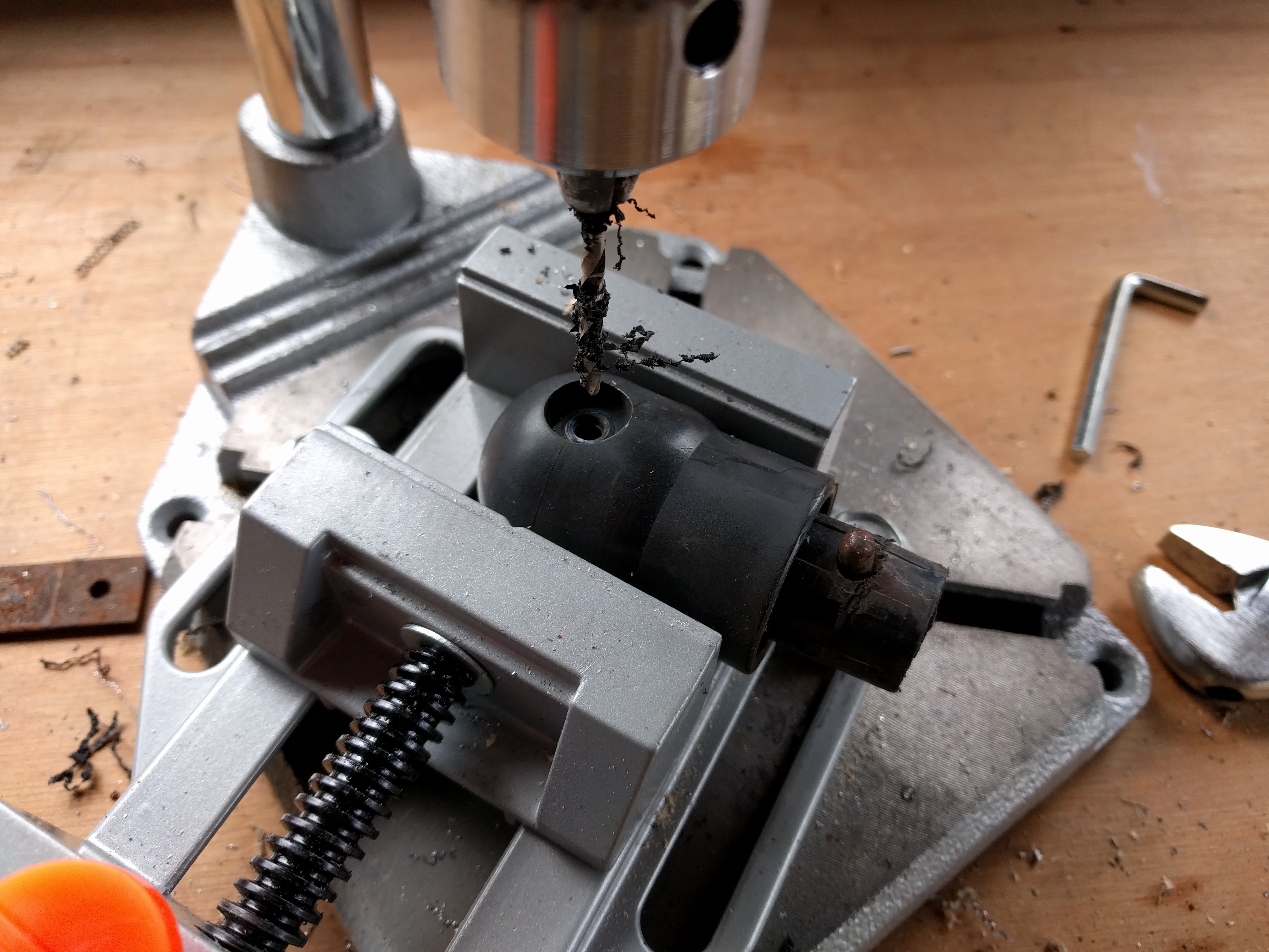
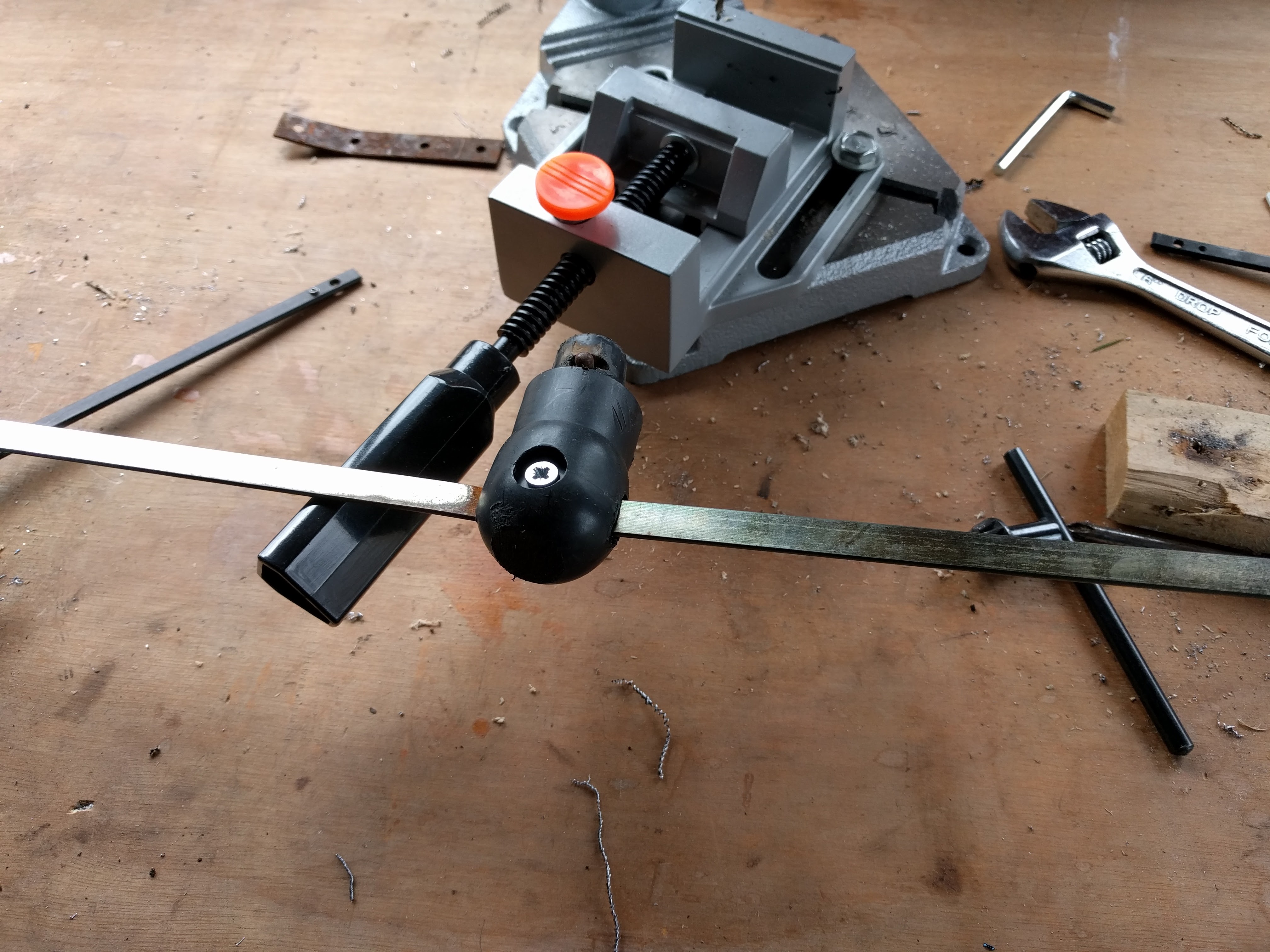
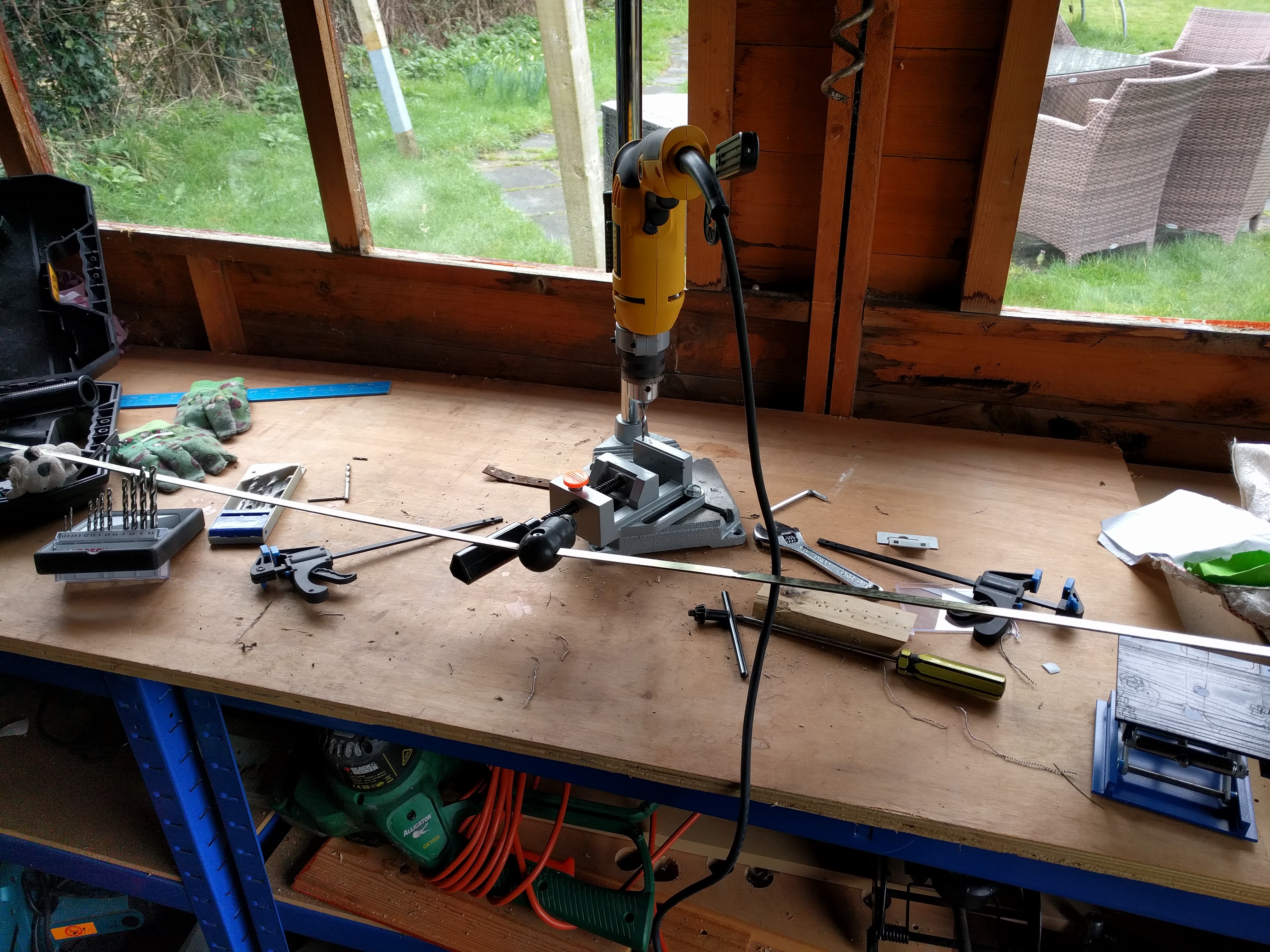
I took out the metal ummm things that held up the netting and drilled holes in them so that I could drive a screw through them and properly fix them to the uprights.
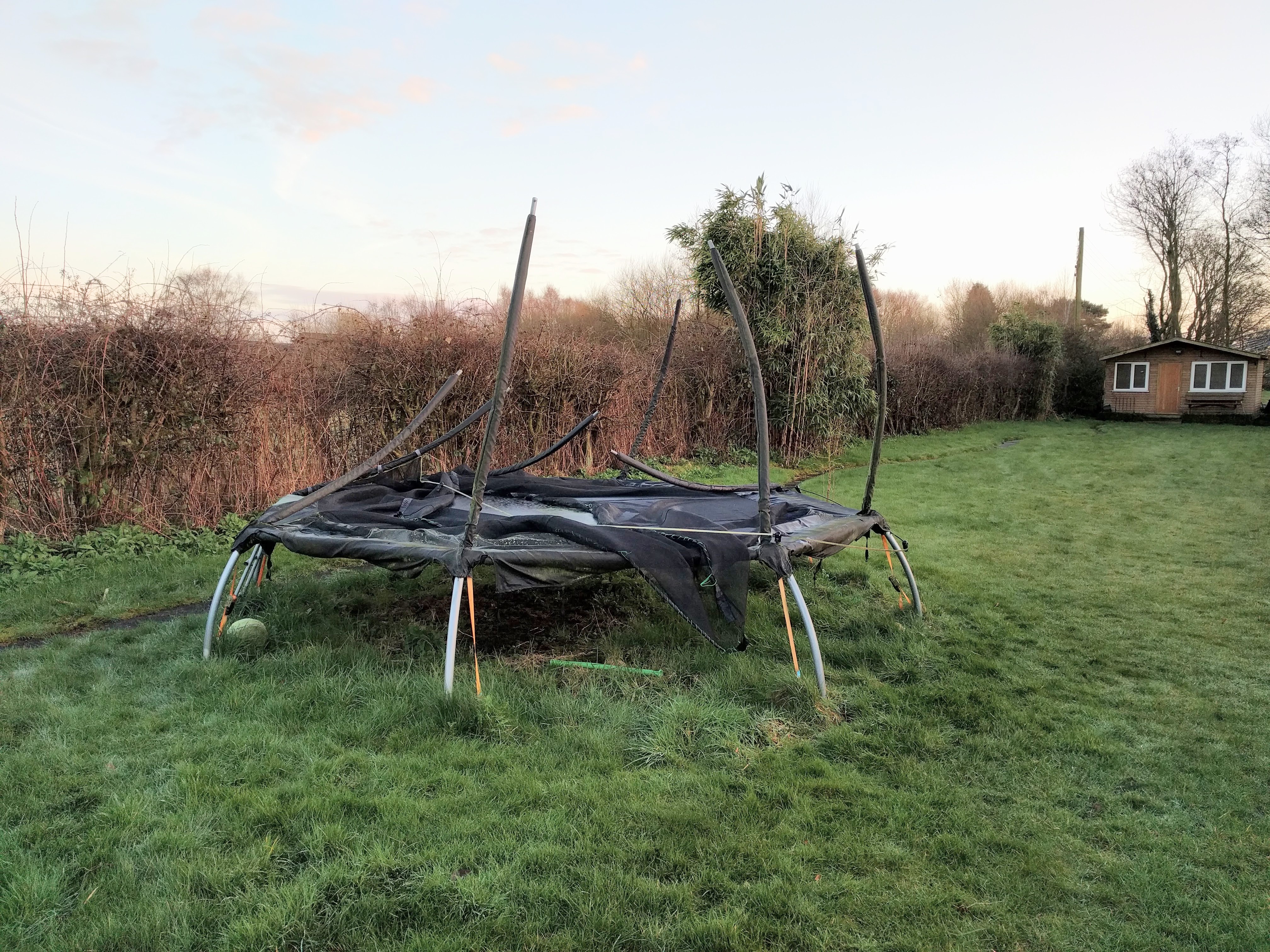
The finished product. I had to use tie wraps to connect the netting back up with the screwed metal things but it’s going to stay up! The thing about TP Toys trampolines is that they’re built for easy erection rather than long term use. The system of holding up the metal things is shockingly bad, the top of the netting wears through in no time and the studs for keeping the uprights vertical are simply shit.
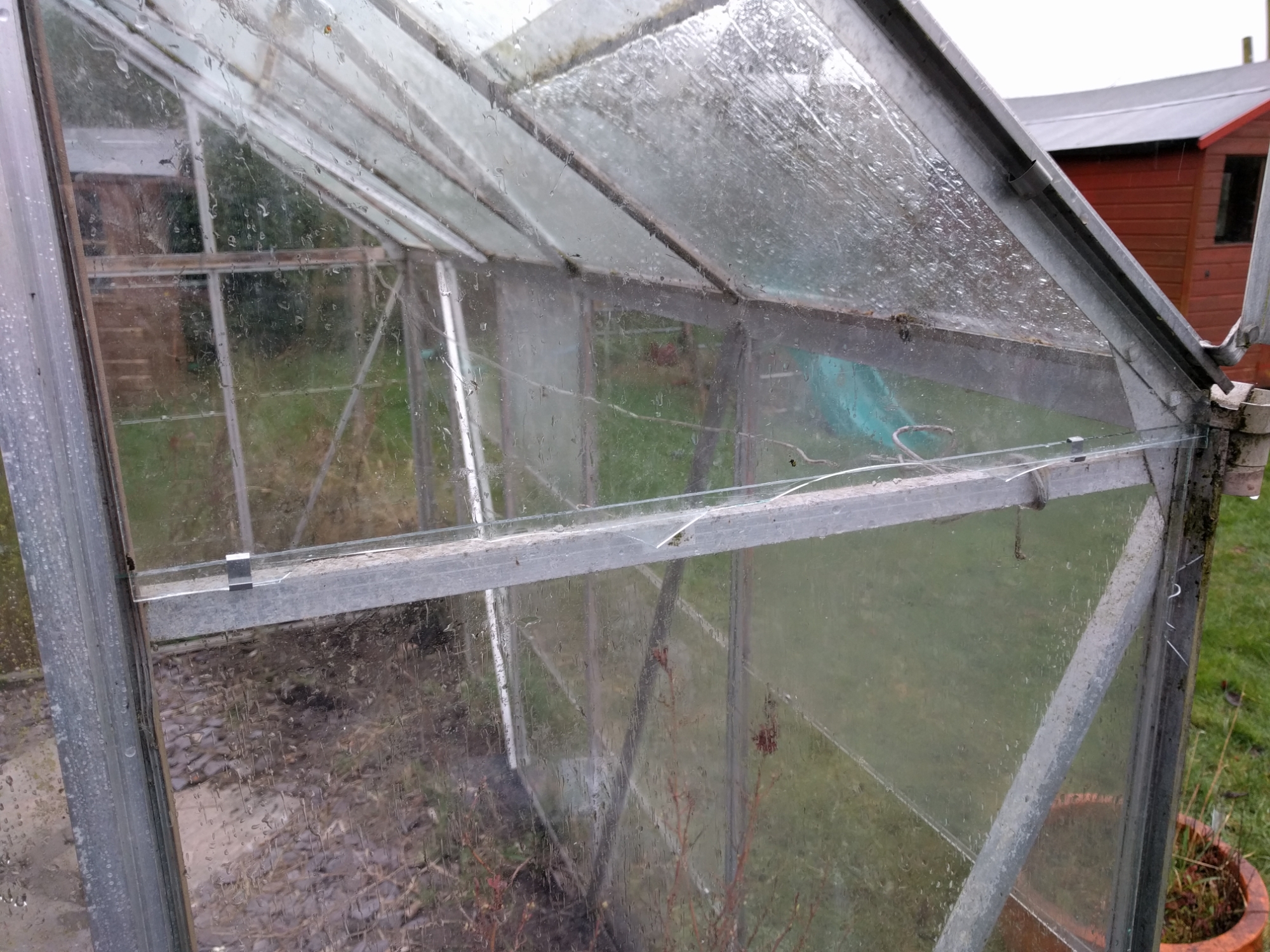
Cutting small pieces is a piece of cake. But whenever I try to cut a big piece it breaks more or less in the right place but with jaggedy bits. So it looks a bit rubbish but at least my greenhouse is now complete with the old wonky bits removed
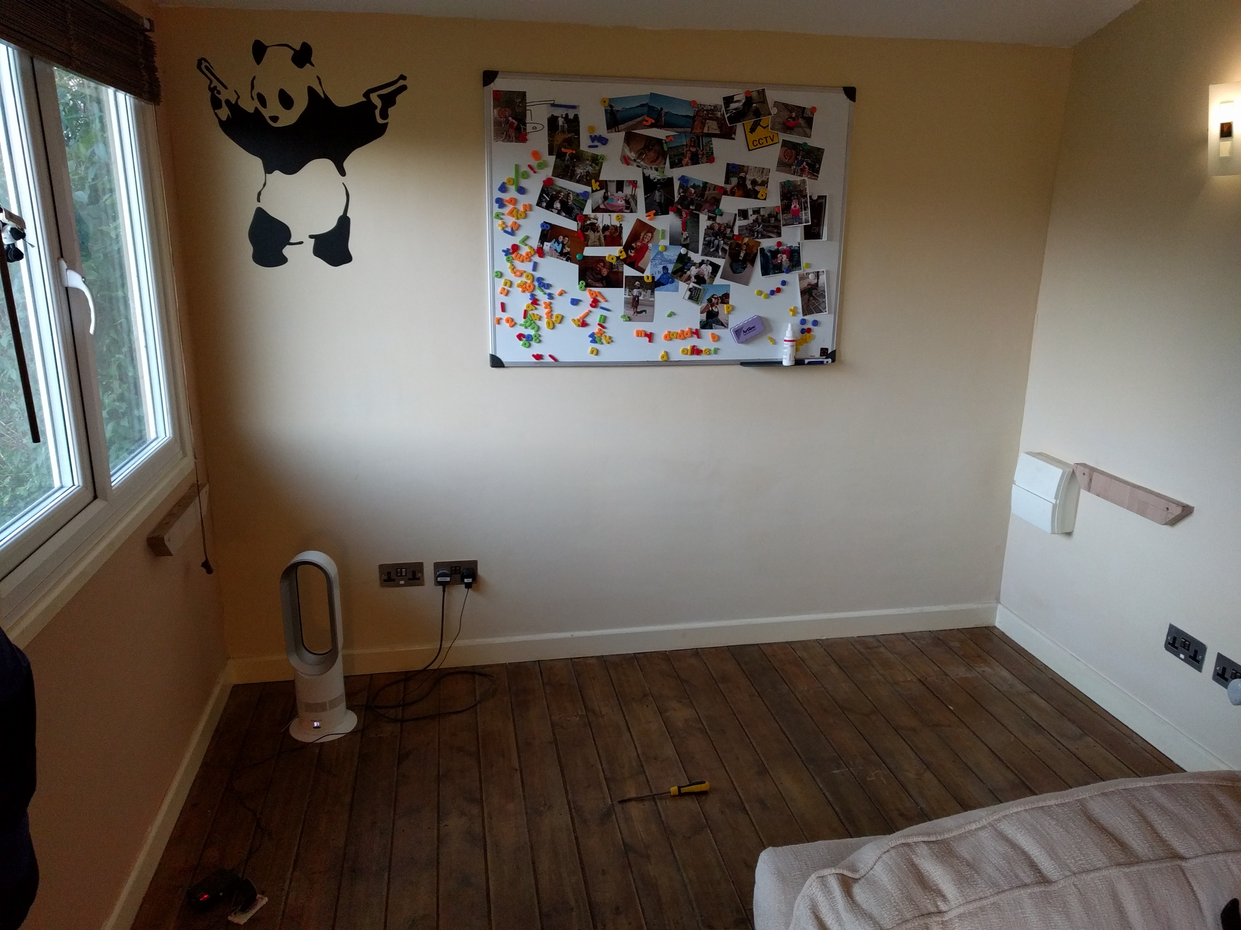
A while ago Oliver asked for some space in my office to build Lego creations. Being the dutiful loving father [ and a little bored ] I decided to indulge him.
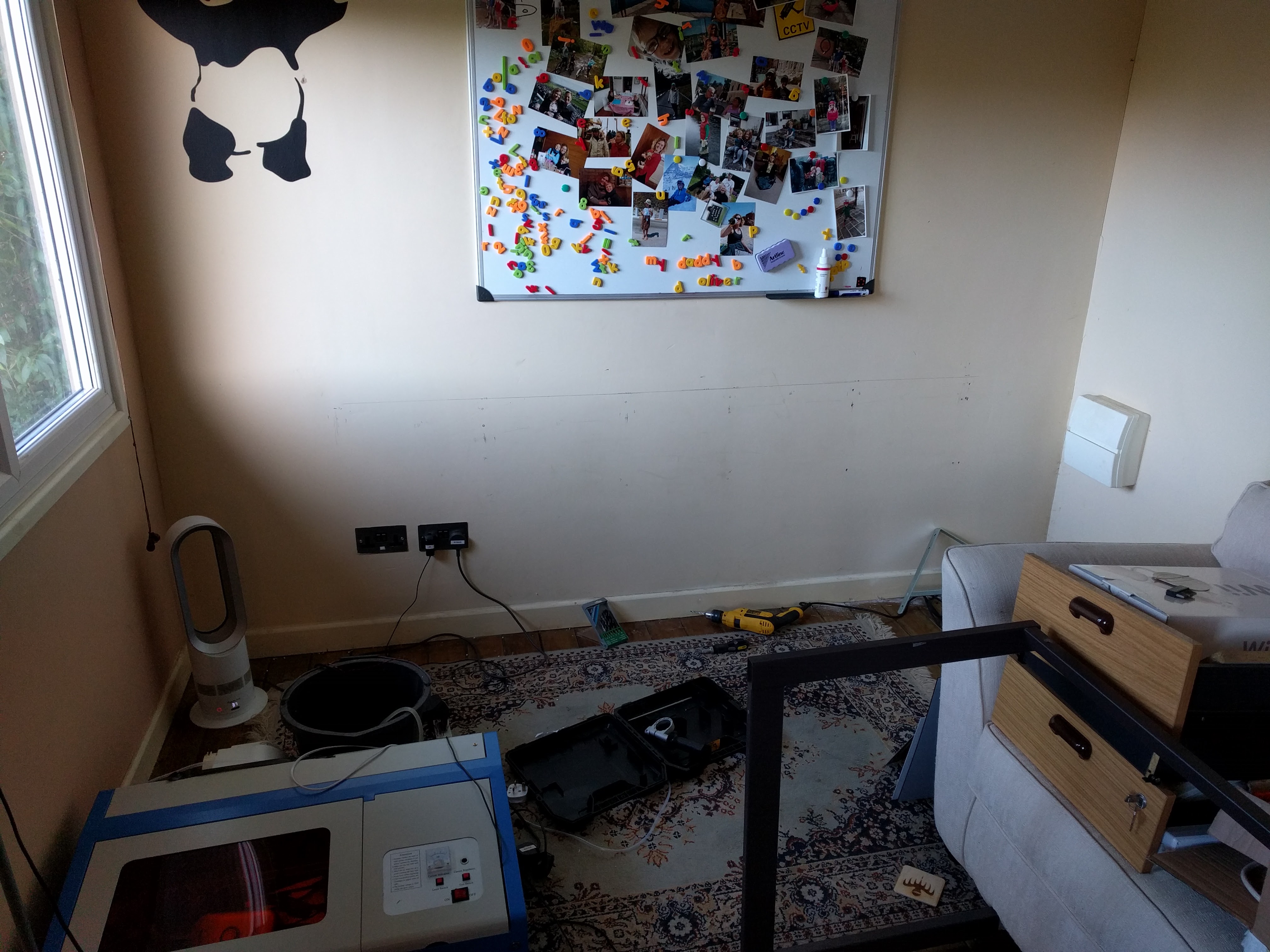
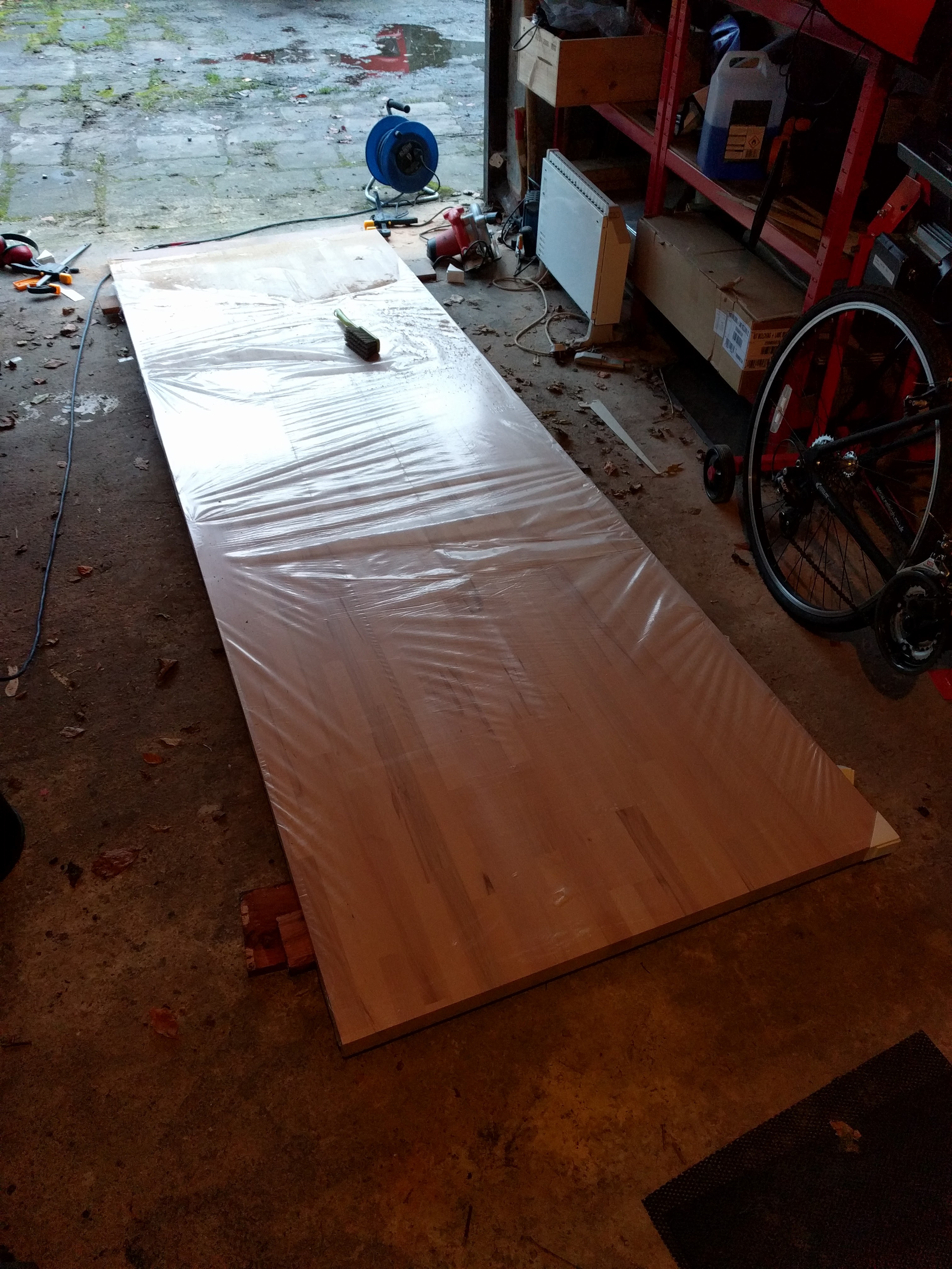
The wood was a 40mm x 900mm x 3000mm piece of birch from eBay which I had to chop down to size in the garage.
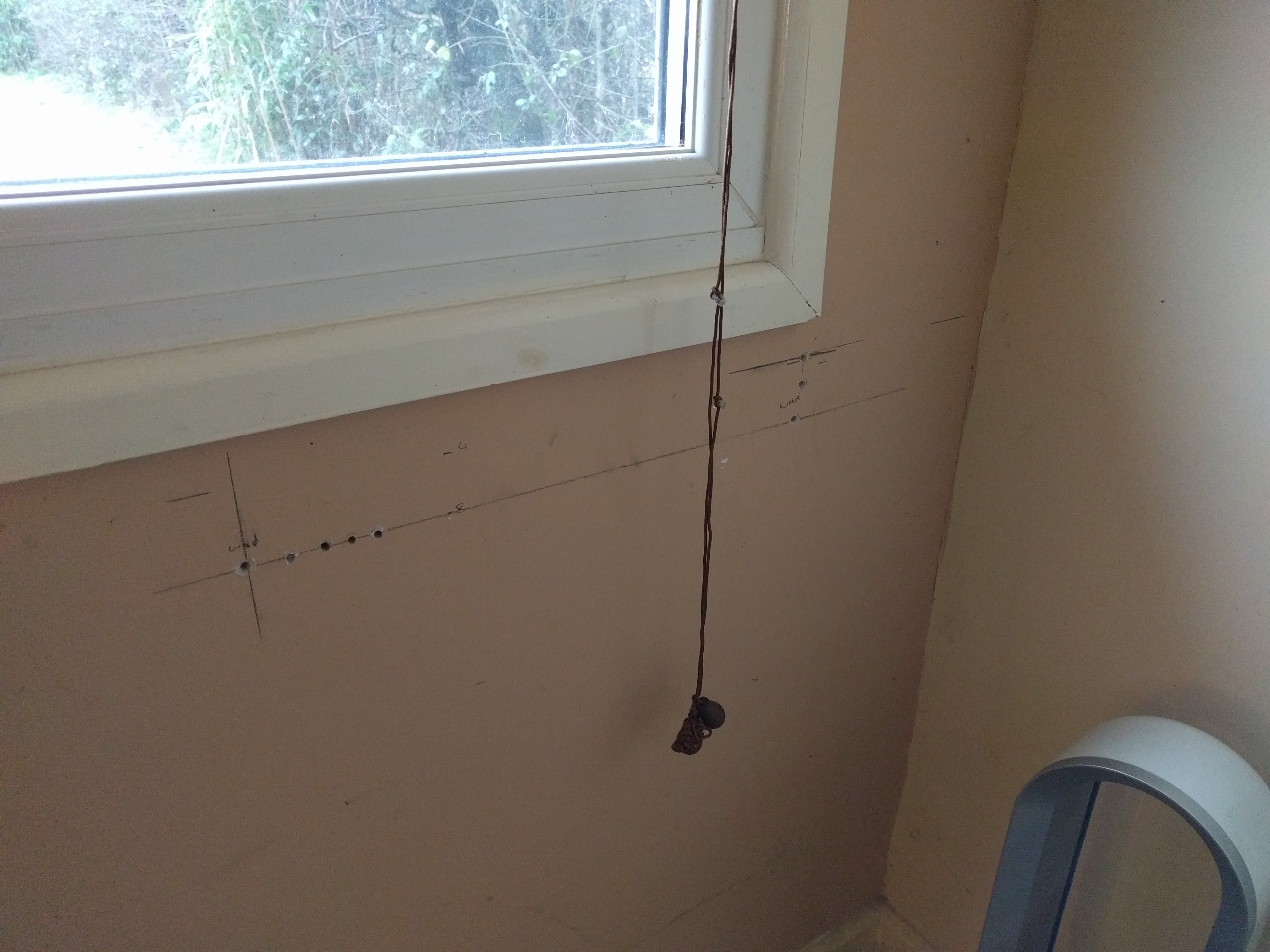
I completely messed up getting the braces in a line. I’m really not very good at that sort of thing.
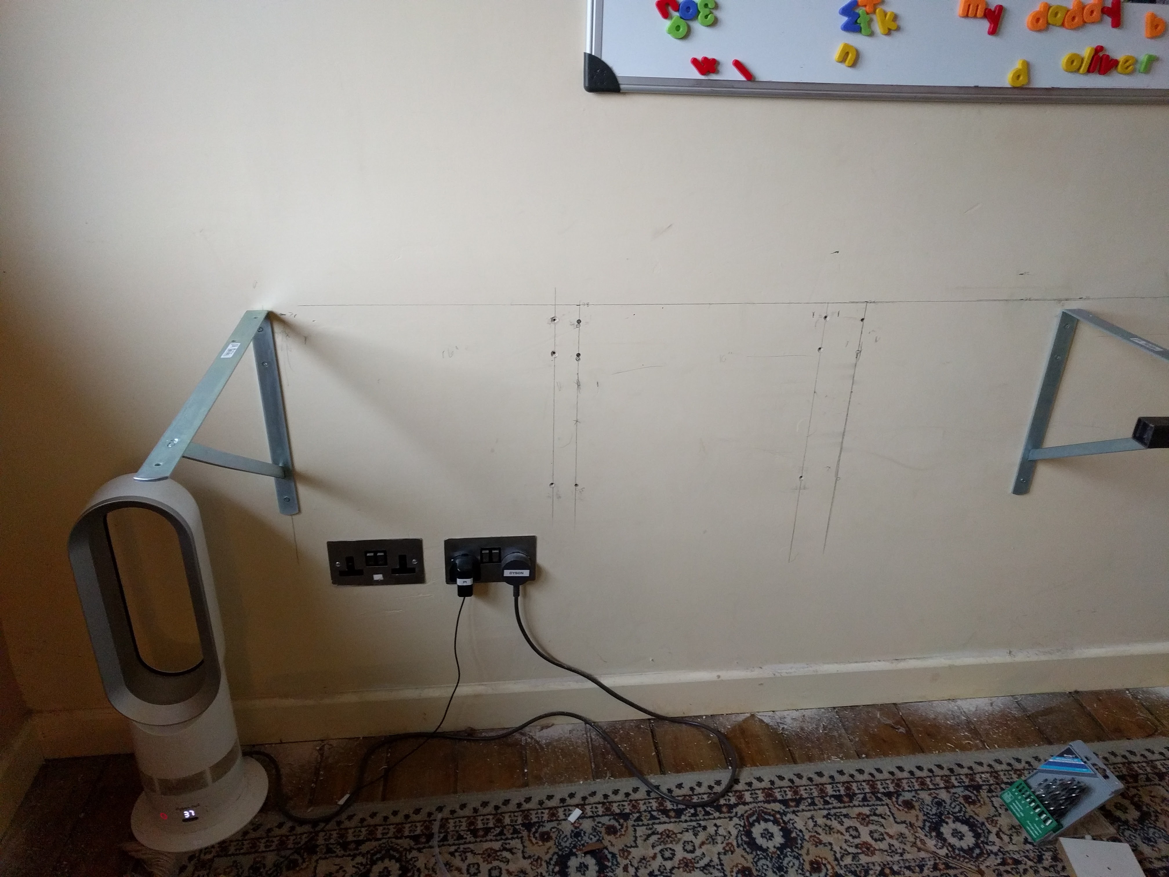
So I eventually went with supports at either end and then worry about making it safe later
Below is not quite the finished item. I had to wait for a hole saw to arrive and then I added 4 x 60mm holes near the wall to keep cables tidy and underneath I installed cable trays so that it still looked neat when all the kit was in place.
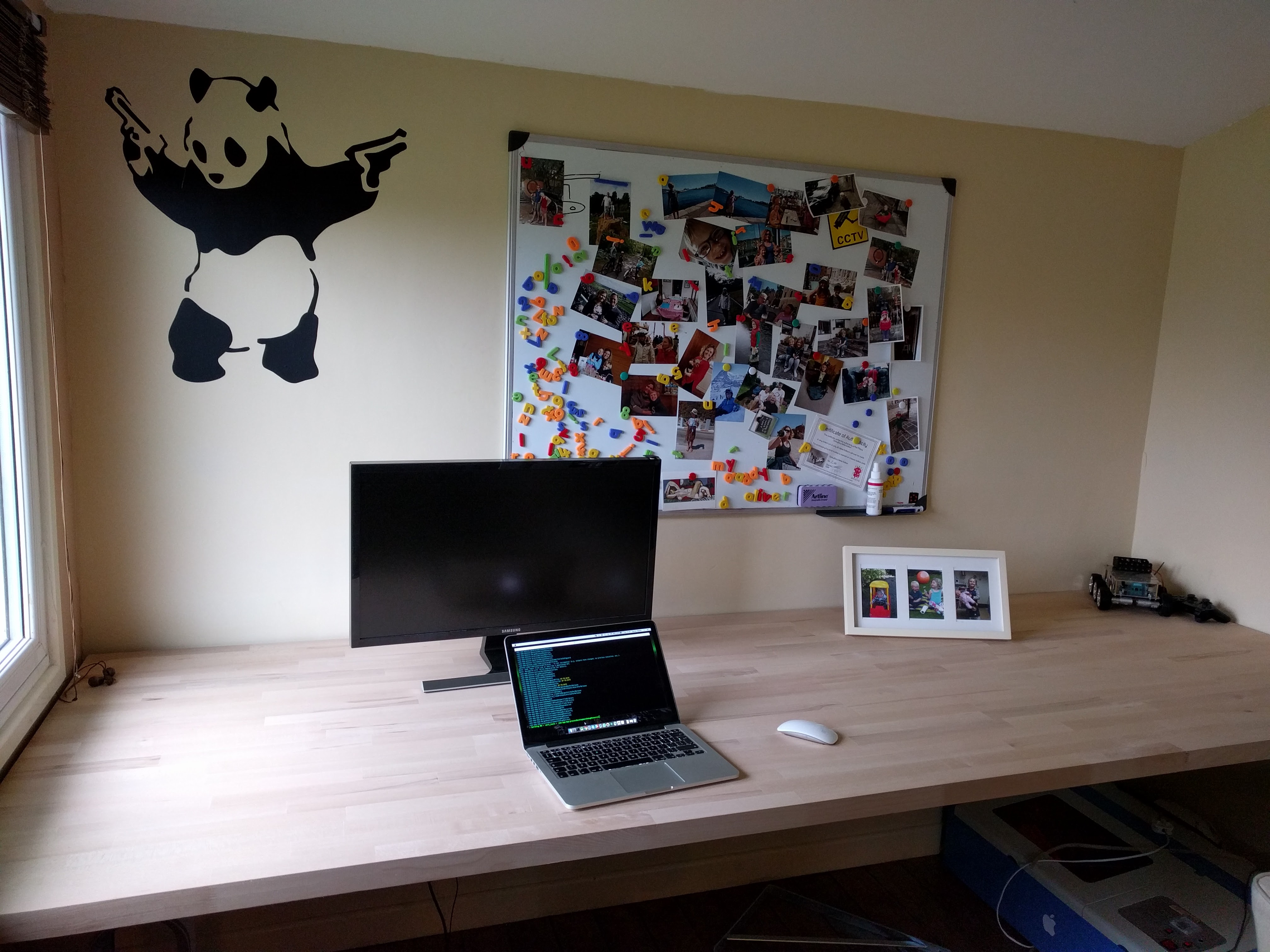
Finally I used a car jack and a stool to lift the whole desk up a little and add some steel supports underneath so the whole thing doesn’t just collapse if somebody sits on it…but I’ve yet to pluck up the courage to sit on it.
Massive thanks go to Mark from #4 who helped me carry to wood from the garage to my office and then came up with the cunning plan of sliding it into place using the sofa bed.
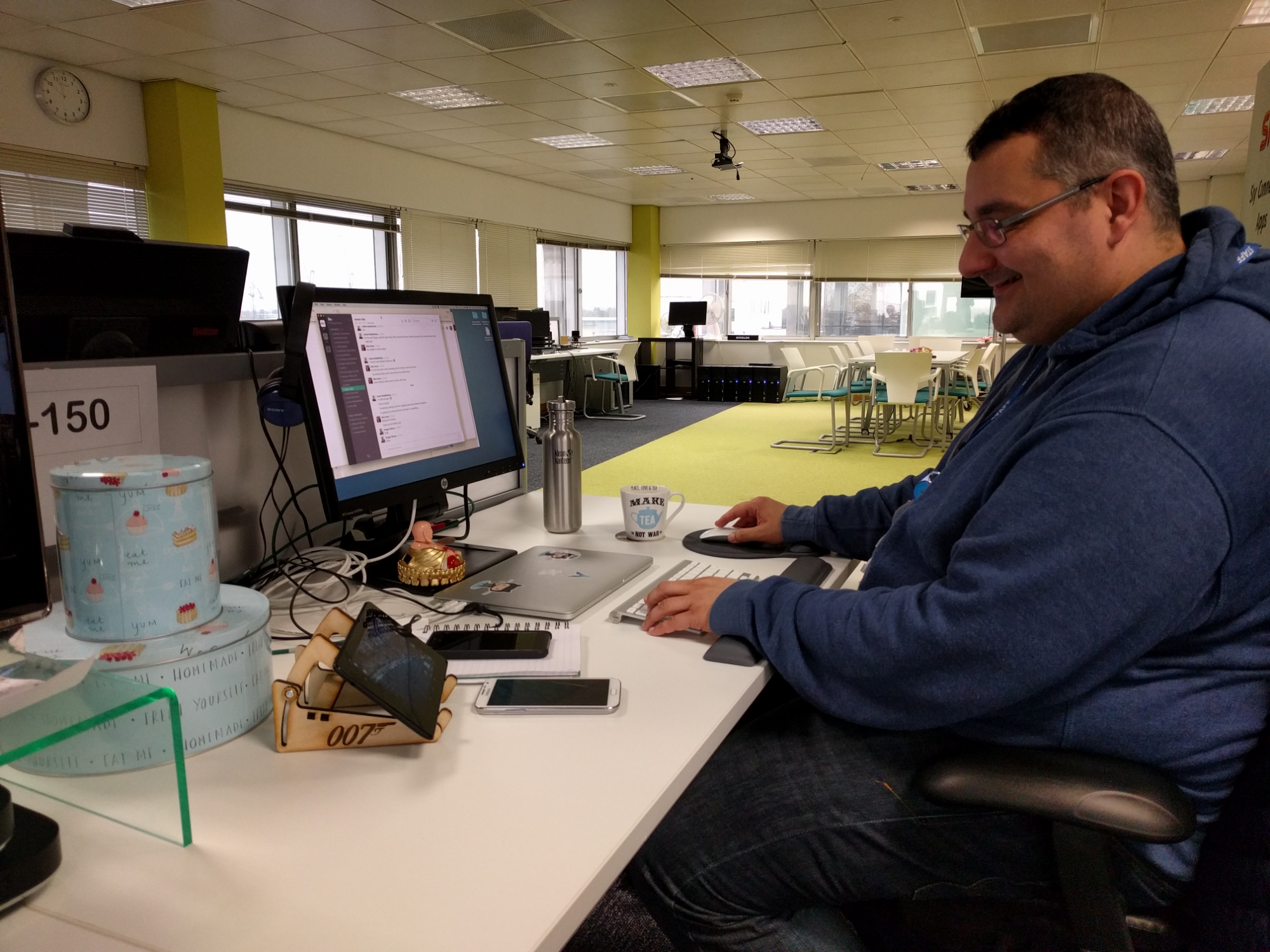
A 007 themed tablet stand has been spotted in the wild with Dragan
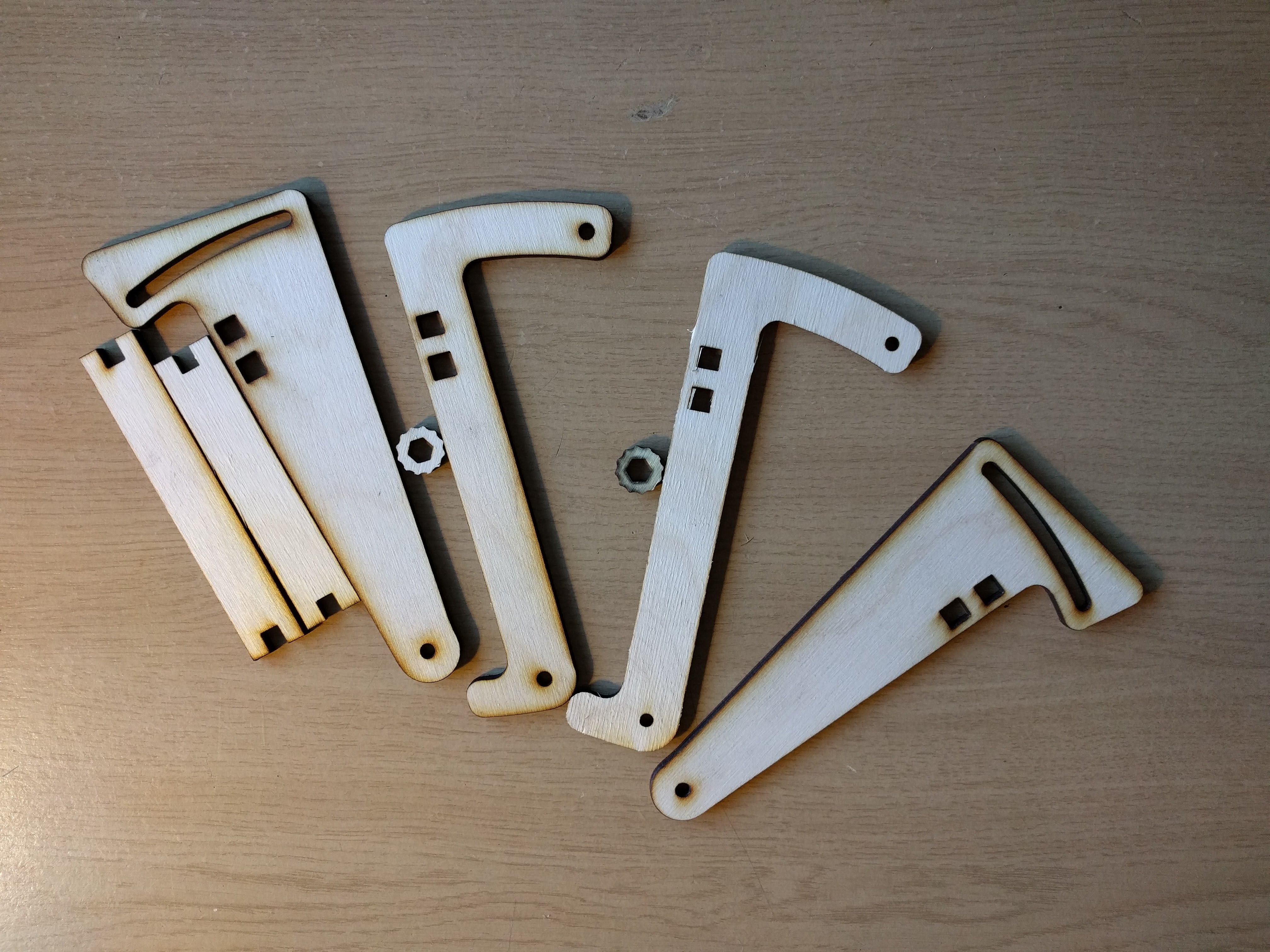
From a rough piece of plywood to the cut-outs below
to this thing of beauty.

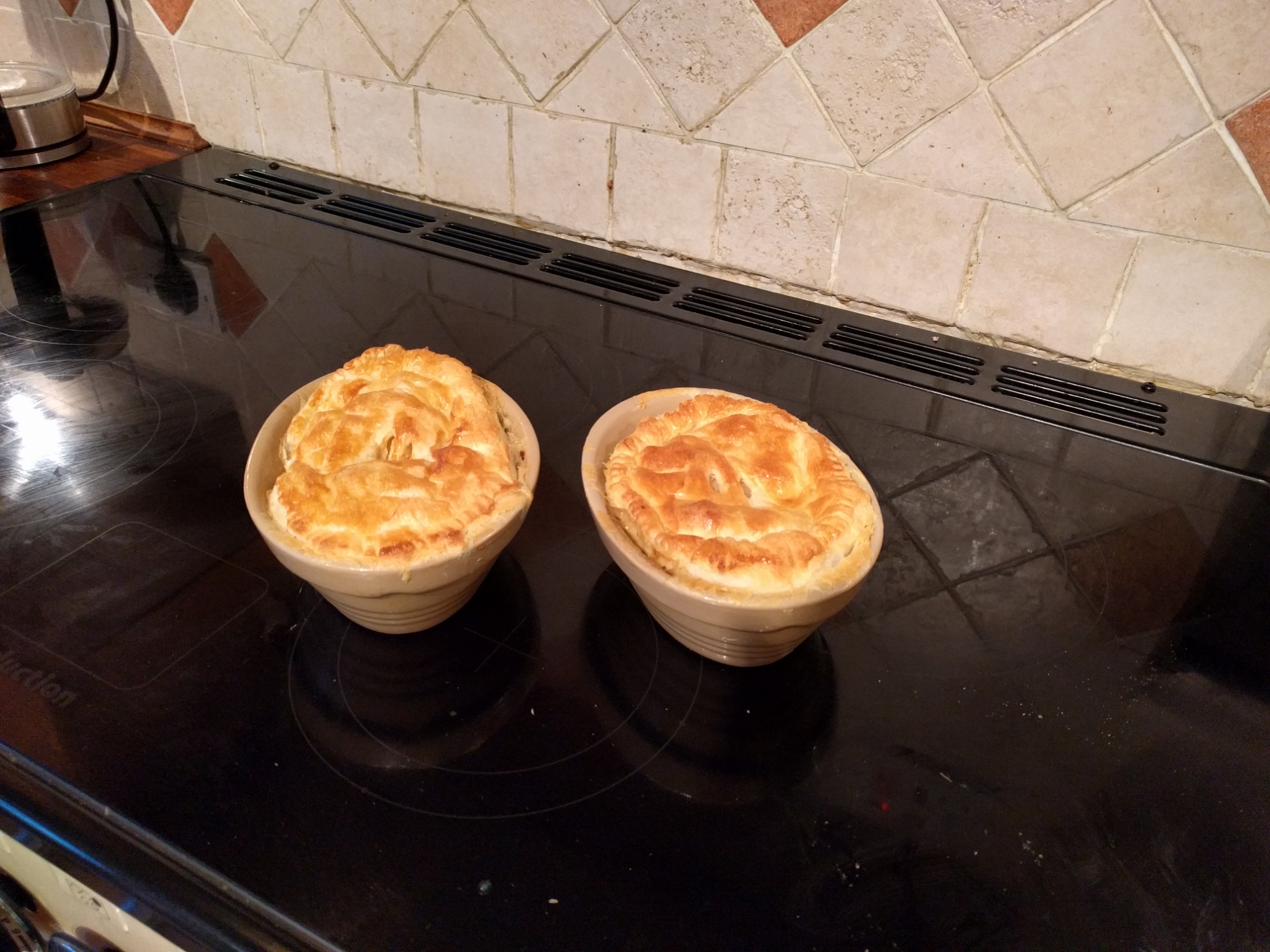
That’ll be the last of the Xmas dinner leftovers then
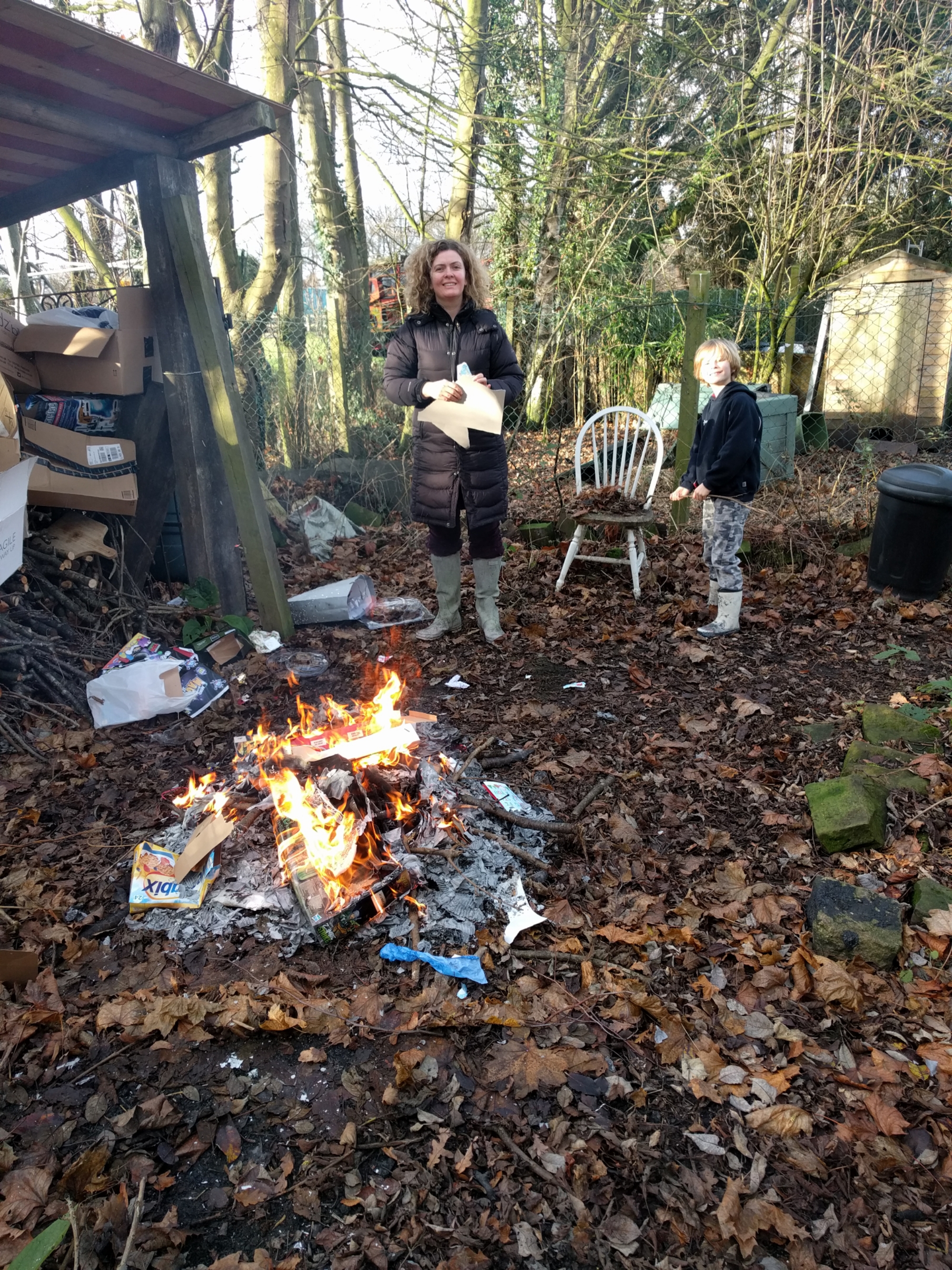
The annual boxing day recycling. It’s become quite the tradition
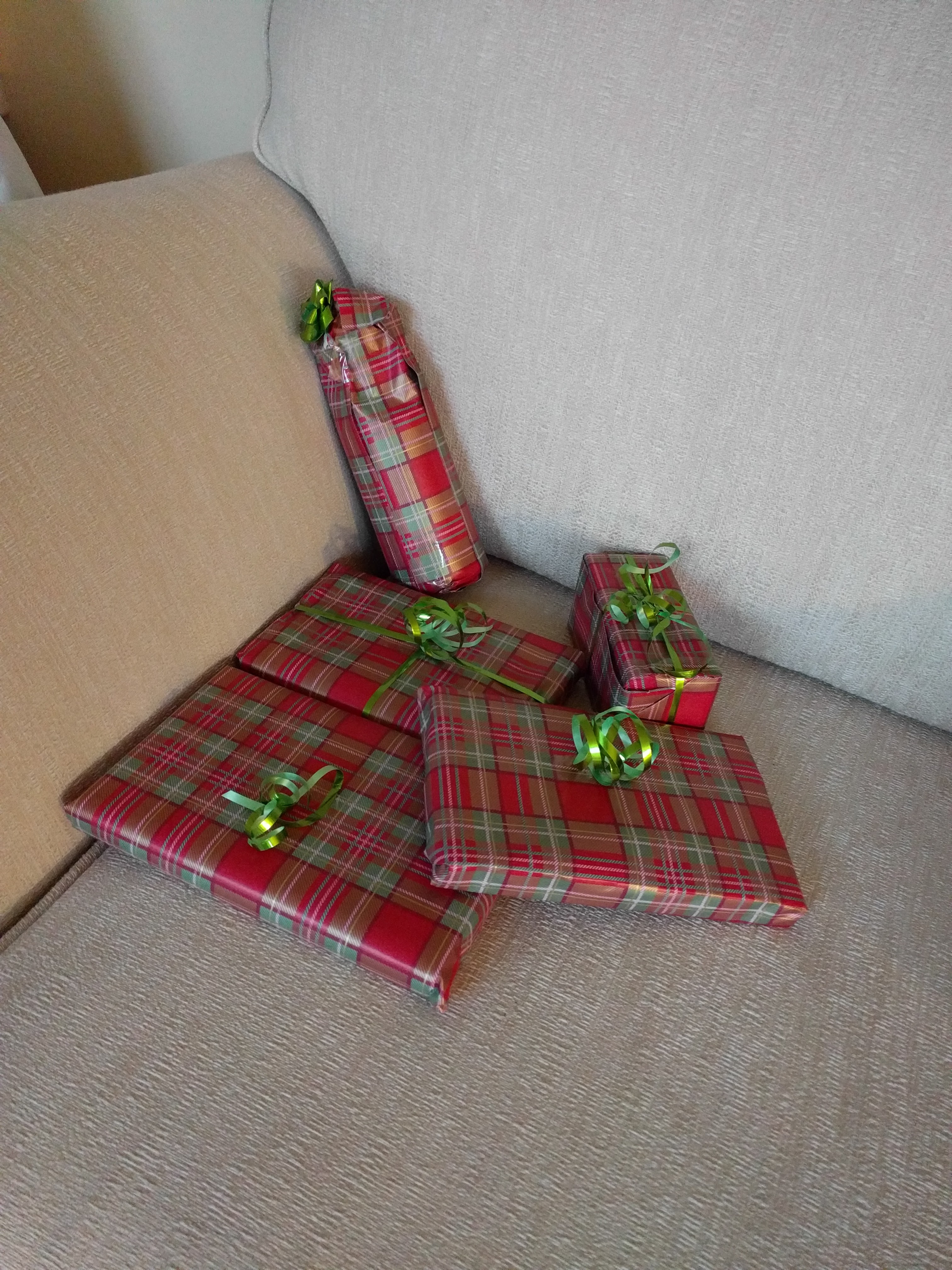
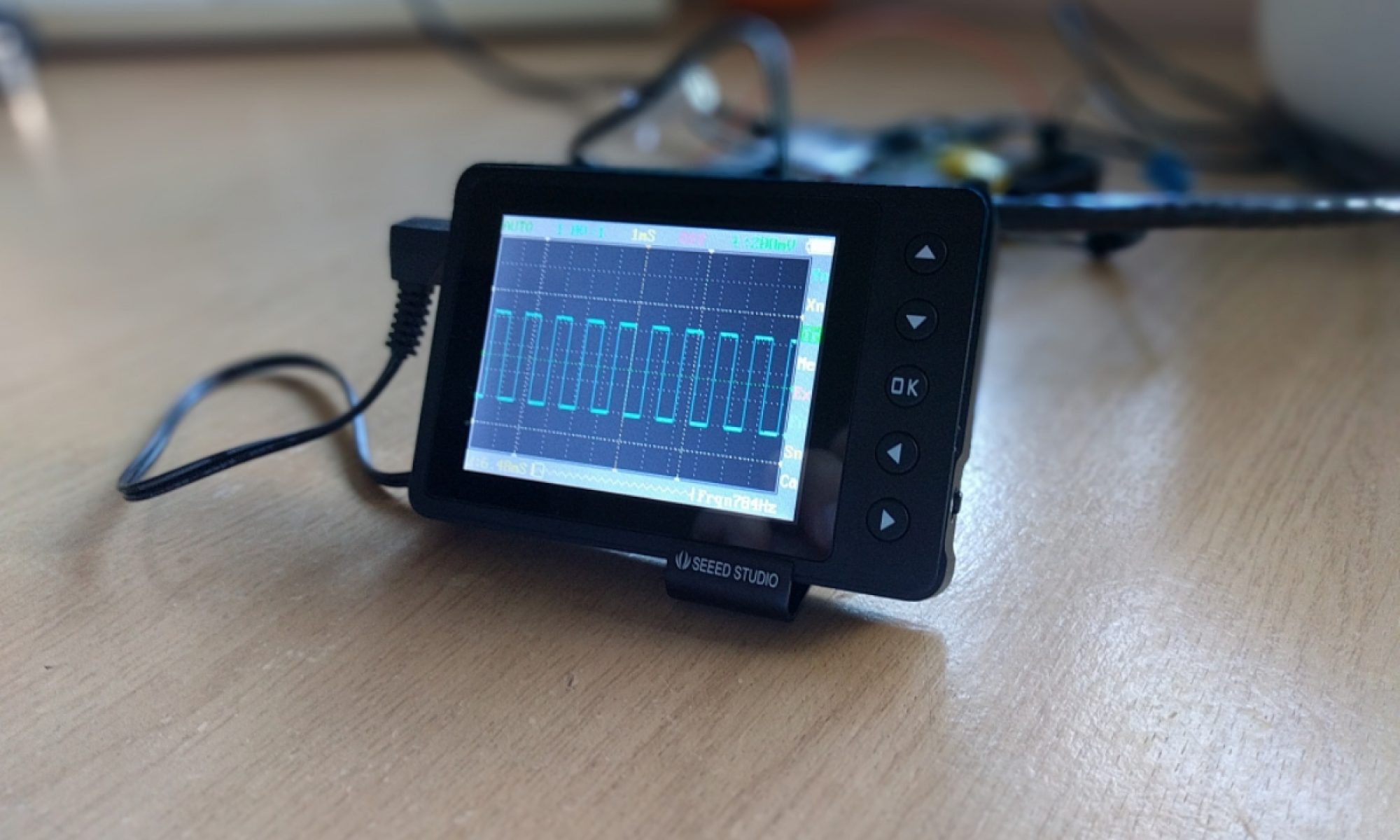
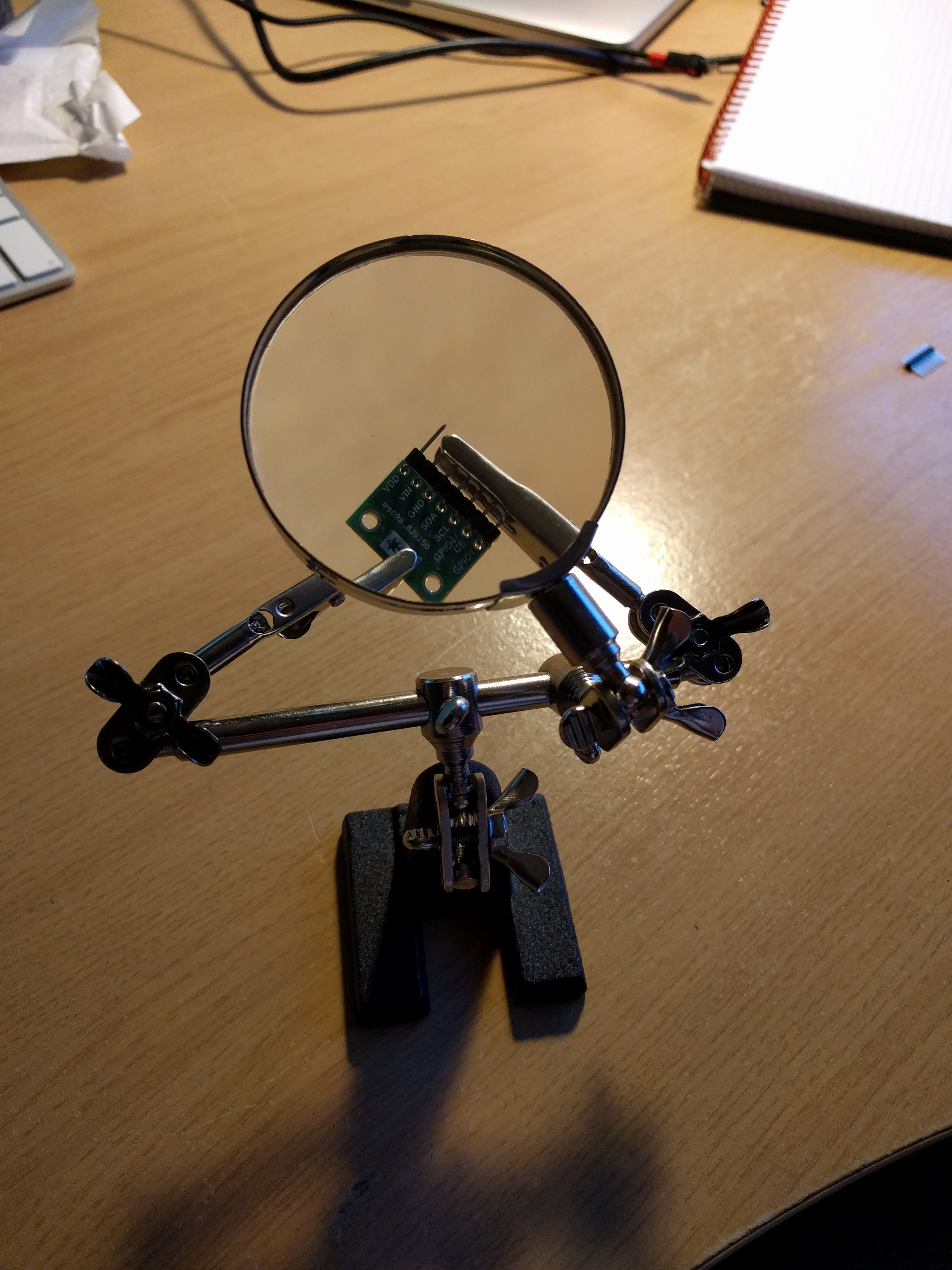
This is how we roll in the Steele house these days. Christmas Eve is spent wrapping presents and soldering time of flight distance sensors to build a hoopy height adjusting gizmo for my raspberry pi / k40 laser cutter.
Now for wine…
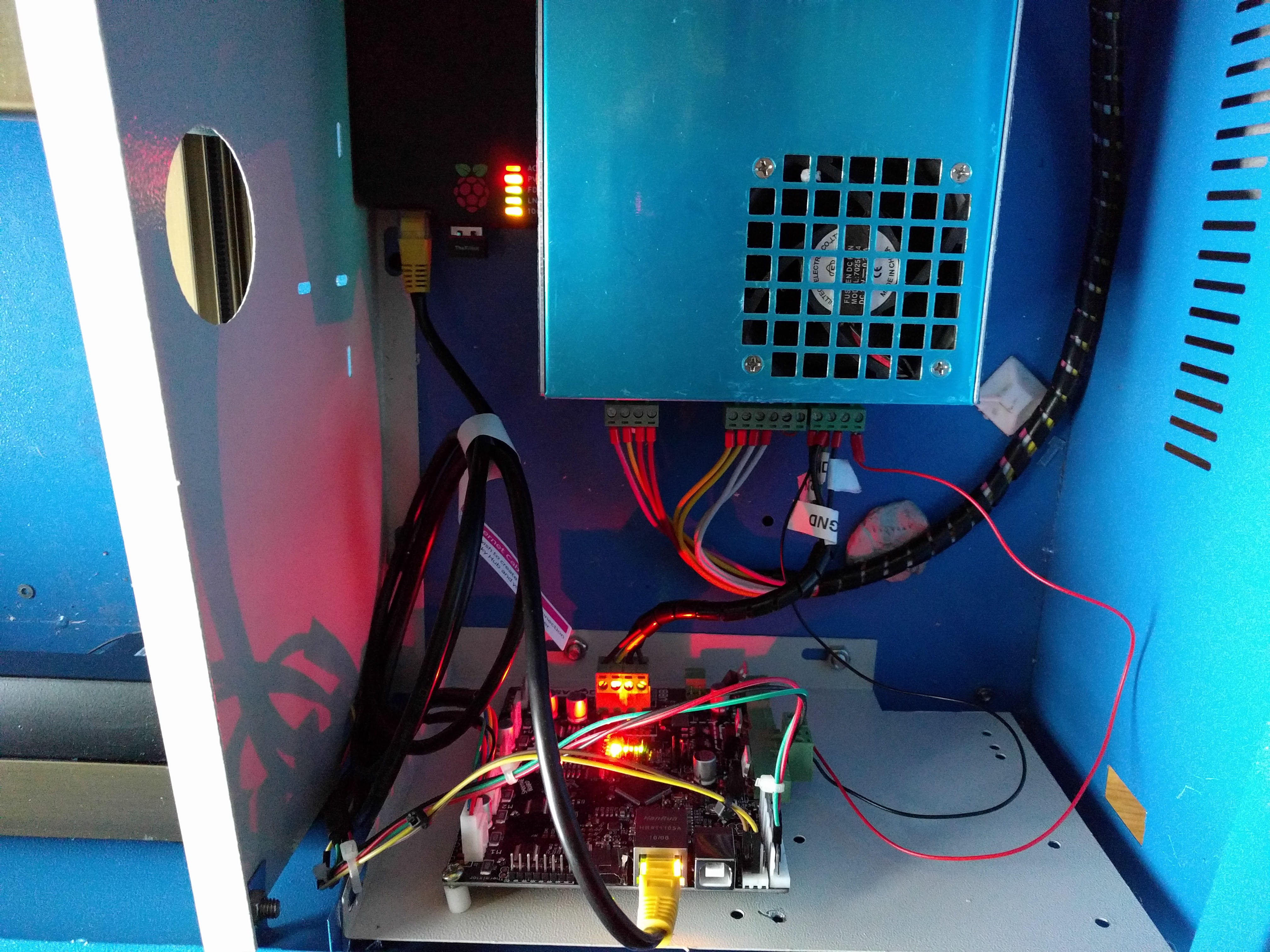
Plenty of people are buying cheap K40 laser cutters from eBay and lots more people have a growing collection of Raspberry Pi’s – I fit into both of those categories.
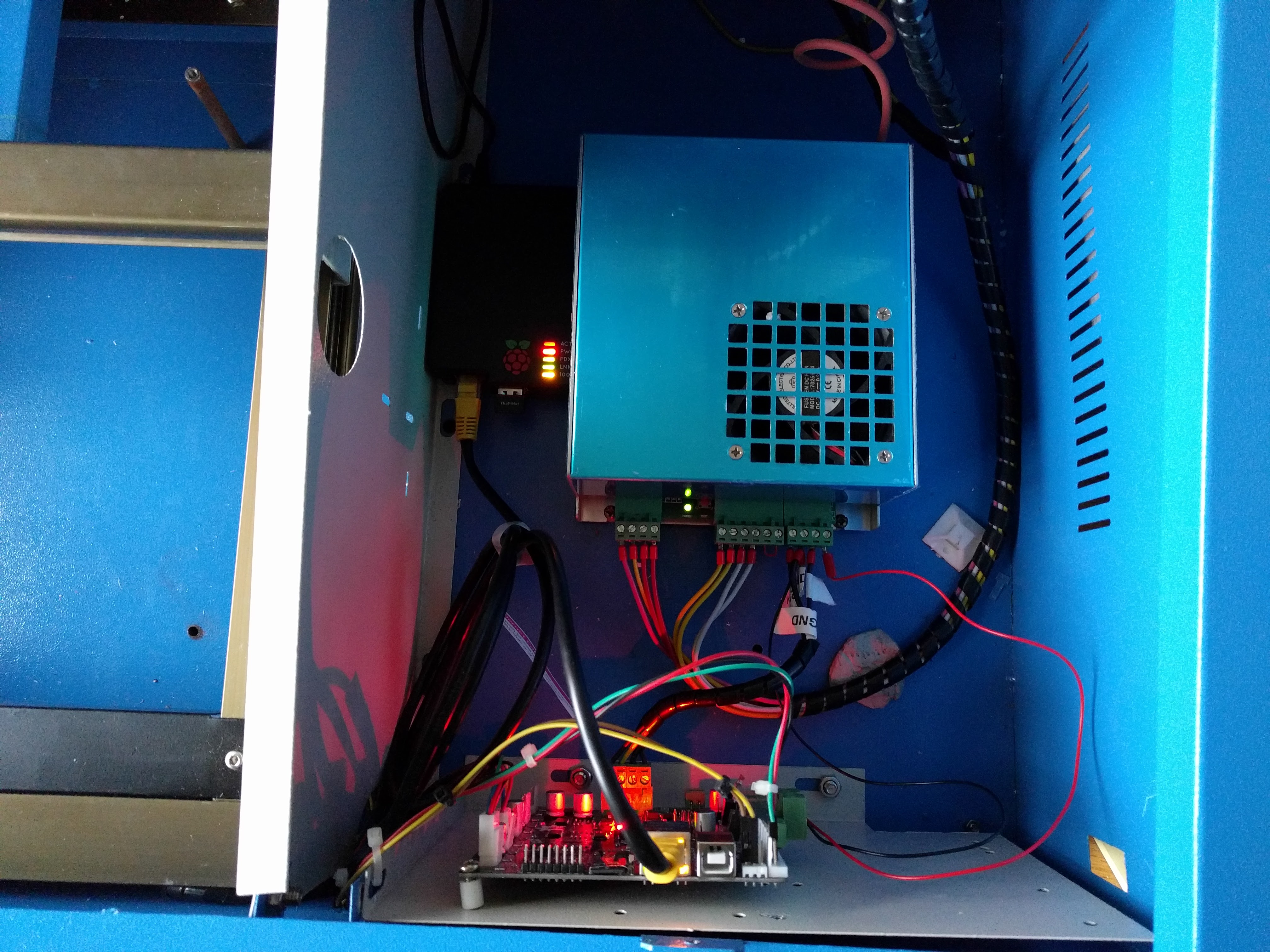
Fortunately I made the decision to replace the stock K40 controller board with a Smoothieboard. This gave me the capability to connect via Ethernet and a whole bunch of other things that made me all excited.
Unfortunately my K40 is positioned on the other side of my “office” so whenever I wanted to use it I had to run an ethernet cable across the room which was very annoying.
It was whilst messing about with a Raspberry Pi I had an epiphany. These things have WiFi and Ethernet built in, surely it can’t be that hard to turn it into a bridge/router/packet-forwarding-death-bringing machine. Turns out it really wasn’t that hard…
I followed this guide which got me 90% of the way.
By the time I had finished implementing the above [ which is really just setting up wifi and ethernet and enabling DHCP ] I was able to telnet from my Mac into my Raspberry Pi and from the Pi I could telnet into the 192.168.2.x domain that my K40 was now sitting on. So that’s nice – but it isn’t what I had hoped for. I want to just telnet in from my Mac, or hit the Pronterface interface or use LaserWeb3 or whatever…straight from my damned Mac.
iptables are your friend
There are several guides online talking about using bridge-utils to accomplish this but I couldn’t get them working, and with hindsight I’m glad I didn’t. If I’d have used the RPi as a bridge then I couldn’t SSH in or do any of the funky magic that I have planned for the future with this K40 such as z-axis manipulation and a full on pretty UI running on a RPi powered LCD touch display, but I digress.
All I really really wanted to do was forward certain ports from the RPi wlan0 interface to the smoothieboard eth0 interface…
-A PREROUTING -p tcp -m tcp –dport 23 -j DNAT –to-destination 192.168.2.10:23
-A PREROUTING -p tcp -m tcp –dport 80 -j DNAT –to-destination 192.168.2.10:80
-A POSTROUTING -d 192.168.2.10/32 -p tcp -m tcp –dport 80 -j SNAT –to-source 192.168.2.1
By adding something along the lines of the gibberish above to your iptables setup file that you created using the “Wifi to ethernet adapter…” then you should be cooking on gas. Basically the prerouting stuff forwards anything received on telnet or HTTP ports onto the smoothieboard. The postrouting stuff is to allow the response from HTTP to make it’s way back to your host machine.
You may have to modify your smoothie config file if it’s currently setup for static IP but seriously, if you’re buying laser cutters, modding the control board and then pondering sticking in a RPi to do wifi bridge/route/death then I’m pretty sure I don’t have to hold your hand and lead you through the config file modifications.
If you need help you can find me on Google+